1
$\begingroup$

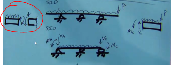
I have been practising the superposition method lately and I am confused in terms of drawing the directions when sectioning. Here is the problem: enter image description here

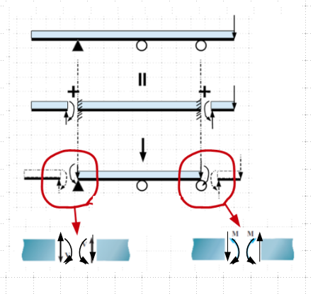
Heres is the process of converting a indeterminate system into a more solvable indeterminate system drawn by my lecturer.

Can someone please explain the direction of shear and moment drawn? For example, Why is it up and clockwise for the sectioning on the left beam? I understand that the opposite side of the beam must have opposite shear/moment.

enter image description here

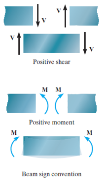
According to my textbook:

enter image description here Shouldn't we assume down and anticlockwise for the left most beam, like this diagram suggests?
$\endgroup$

1 Answer 1

1
$\begingroup$

This is the first step to simplify the analytical model by applying the equivalent load concept as depicted below:

enter image description here

Another way to examine the direction of forces at where the cantilever is cut off.

enter image description here

$\endgroup$
9
  • $\begingroup$ Hi r13 Yes, I understand the simplification part. Can you please explain more about the directions? Why is it down and anticlockwise on the left most support and down and clockwise on the right most support? How do you get the directions? $\endgroup$
    – CountDOOKU
    Commented May 7, 2022 at 1:37
  • $\begingroup$ First to separate the left side cantilever from the main structure, what are the reactions required at the support/cut to maintain equilibrium (hint: sum Fy = 0 & sum M = 0 at the joint? Now, these reactions act on the main structure as applied load with directions reversed, so if we put the cantilever back, the forces cancel out maintaining internal equilibrium, similar to take a cut at any location within the beam, the forces at the left of the cut must be equal to forces to the right of the cut with reversed direction [VL+(-VR)] = 0 & [ML+(-MR)] = 0, the "-" represents reverse of direction. $\endgroup$
    – r13
    Commented May 7, 2022 at 2:33
  • $\begingroup$ If you have difficulty reading my explanation, see your own graphs for V and M at a beam cut - a pair of V & M in the reverse direction, so sum forces = 0 at the cut. $\endgroup$
    – r13
    Commented May 7, 2022 at 2:52
  • $\begingroup$ isn't that in the opposite directions? In my diagram, the shear force is down,up. But in your diagram the left most sectioned beam is up,down? Like why is it in the opposite direction of the positive shear? Same goes with the moment, why don't we assume positive moment and positive shear first? $\endgroup$
    – CountDOOKU
    Commented May 10, 2022 at 14:59
  • $\begingroup$ I see what has caused the confusion. I attached your diagram just to show the relationship of forces on the faces at the section cut, however, I didn't change the direction of the forces to match the real problem. I apologize for my negligence, please see the revised diagram. $\endgroup$
    – r13
    Commented May 10, 2022 at 15:55

Your Answer

By clicking “Post Your Answer”, you agree to our terms of service and acknowledge you have read our privacy policy.

Not the answer you're looking for? Browse other questions tagged or ask your own question.