1
$\begingroup$

Can someone please point me in the right direction.

I am a newbie when it comes to statics. I am trying to understand the following diagram.

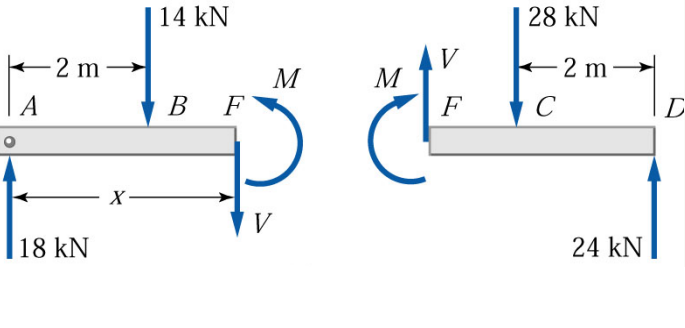
enter image description here

Why on the left side of the beam section, the moment is in the opposite direction to the force (V). But, on the right side, the moment is in the same direction as the force (V)?

Does this have anything to do with external moments?

Please tell me what I should be studying. Thanks.

$\endgroup$

3 Answers 3

1
$\begingroup$

As the name of the subject, "Statics", suggests, the beam and every piece of the segment (AF & FD), that is imaginarily separated from the beam, must stay static in its own system. In structural terms, it means the beam and the segments must remain in "structural equilibrium", either in the global scene/system, or the local scene/system, the equilibrium requirement is satisfied when $\sum F_x = 0$, $\sum F_y = 0$, and $\sum M = 0$.

Before get to answer your question, we need to designate the positive direction of forces with respect to the Cartesian Coordinate System (x, y, and z axes). Commonly, a force is positive in the same direction as "x" and "y" axes (arrow pointing up and right respectively); the moment is positive when rotate counter-clock-wise (CCW) about the "z" axis.

Now let's first check the beam to see whether it is in the state of equilibrium. THe answer is "yes" (see the top figure on the sketch below).
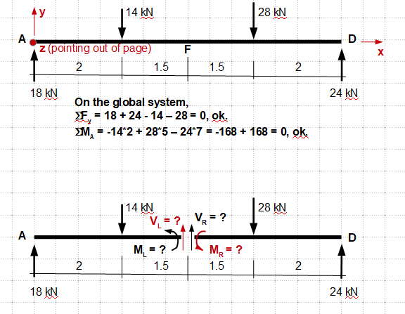
enter image description here

Next, let's break the beam at point "F" (the bottom figure). Note that I've placed all the internal forces on both sides of joint "F" in the positive direction.

- Now let's write the equilibrium equations for the left segment,

$\sum F_x = 0, -14 + 18 + V_L = 0$, then solving

$V_L = 14 - 18 = -4$, here the minus sign indicates the force is pointing down rather than the direction drawn (up), so it needs to be corrected on the sketch to maintain balance.

$\sum M_A = 0, -14*2 + (-4)*3.5 + M_L = 0$, solving

$M_L = 28 + 14 = +42$, the positive sign indicates the result is in agrement with the direction shown on the sketch (CCW).

- Similarly, let's write the equilibrium equations for the right segment,

$\sum F_x = 0, -28 + 24 + V_R = 0$, then solving

$V_R = 28 - 24 = +4$, the direction of the force drawn is correct (up).

$\sum M_D = 0, -28*2 + 4*3.5 + M_R = 0$, solving

$M_R = 56 - 14 = +42, $M_L$ rotates CCW, the direction drawn is incorrect.

Next, let's summarize the internal forces with their corrected directions:
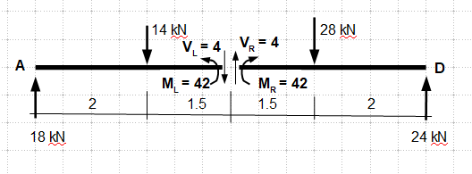
enter image description here

Note, the directions of the forces are in agreement with the sketch you've provided. Now you should know what is the governing factor, and its importance, - "structural equilibrium requirement".

Final (sanity) Checks -

Left Segment:

$\sum F_y = -14 + 18 -4 = 0$

$\sum M_A = -14*2 - 4*3.5 + 42 = 0$

Right Segment:

$\sum F_y = -28 +4 -24 = 0$

$\sum M_D = -28*2 + 4*3.5 +42 = 0$

Done.
$\endgroup$
0
$\begingroup$

The reason why this the forces and moments are opposite, is that the cross-section on the edge belongs to both the right and the left. (I tend to think of it as an imaginary infinitesimally thin section, although it's not strictly correct).

Additionally this cross-section is "static" in space. Therefore the sum of forces should be equal to zero.

So the forces and moments acting on one side are acting on the other.


A more correct approach is to consider it is the following: when the section is made (and the beam is broken up to left and right), right at the end there should be forces acting from the other side.

Because of Newton's laws, every action produces an equal and opposite reaction. So if the left part applies a 10 N force to the right, then the part on the right applies a 10 N force to the left.

$\endgroup$
0
$\begingroup$

The moments on the two sides of the FBD are the sum of the area of shear before the two sides of the cut, they are always acting in opposite directions to restore the beam from a curved deflection to the straight line.

They have no direct relation to the shear if that has confused you.

So that you can imagine how the shear is not related to the moment consider a cantilever beam with a load P at the end. so the shear is constant along the length, $v=P , $ and FBD at point X as we move to X+dX the shear is the same but the moment on the section is increased.

And if our drawing of FBD (free body diagram) is correct they will be equal and opposite (otherwise the section will turn). Their sign convention is anticlockwise doesn't have anything to do with the sheer convention, up or down.

$\endgroup$

Your Answer

By clicking “Post Your Answer”, you agree to our terms of service and acknowledge you have read our privacy policy.

Not the answer you're looking for? Browse other questions tagged or ask your own question.