1
$\begingroup$

In the statics lesson, we do not think about the effects of forces on objects. In other words, we do not assume that an object can break, bend or twist. In the same situation, we can combine different forces into a combined force. However, the forces can cause different internal forces and deformations on the materials depending on where they are applied.

I will share some examples below. To what extent can the internal force diagrams that I consider in these examples be accurate?

enter image description here

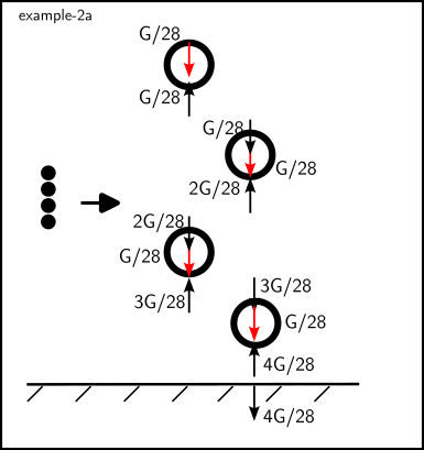
  • As seen in Example-1, an isotropic material rests on the ground as in the figure. Here we need to examine the forces acting on the ground to locate the normal force. First, I divided the material into small pieces and showed the forces due to weight along the black line. (example-2a)

enter image description here

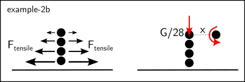
  • Now, as in the theory of elasticity, can we show a weight-induced tensile stress along this line on the diagrams?(example-2b)

  • In another question, we do not say that there is a moment on this object in the classical statics lesson. but when examining the internal forces, can we say that the parts create a bending moment on each other?, of course, this moment is balanced by the reactions coming from the ground.(example-2b)

enter image description here

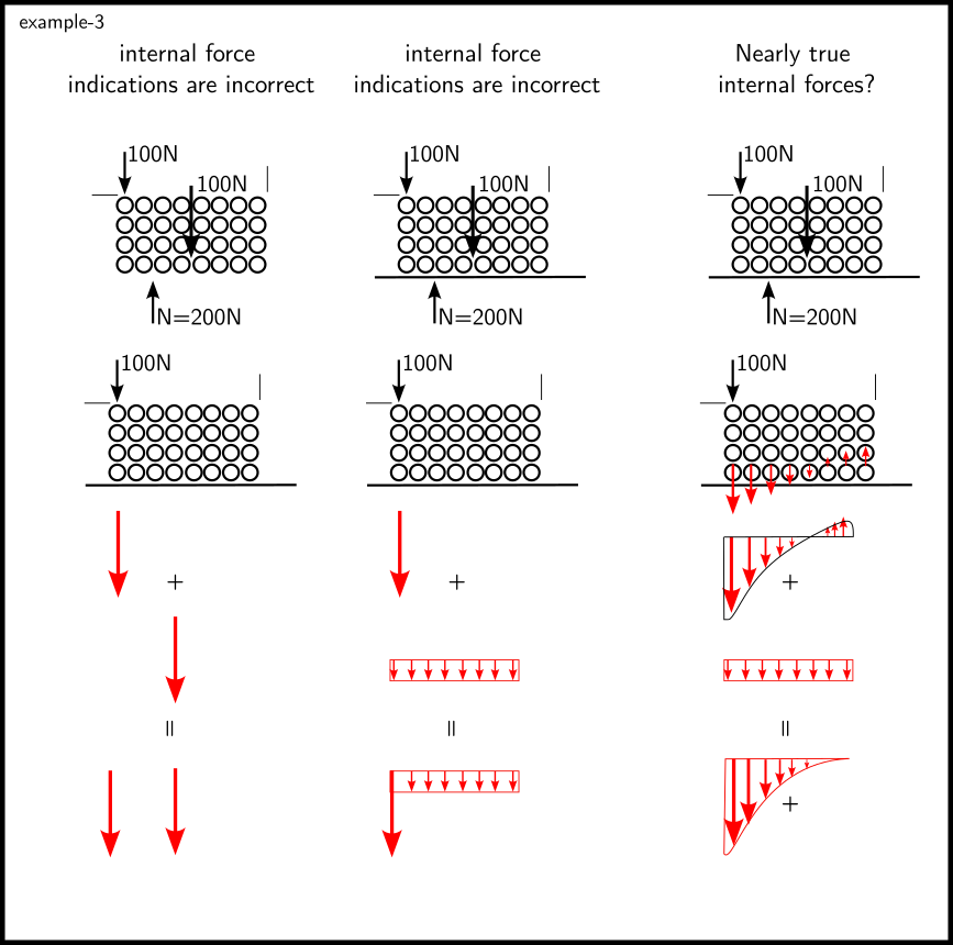
I give another example. Here, a force other than weight is applied to the object. The normal force will be located between the center of gravity and the force. I made the following diagrams to show the compressive forces acting on the ground. The singular forces we showed in statics are not correct for internal force diagrams. Again, I think that the diagram showing the singular force acting on the ground singularly is wrong. For this I made the diagram shown in the 3rd column.(example-3)

  • Do you think the diagrams in column 3 are correct? Here I have created compressive and tensile stresses inside the object due to the singular force acting on the left. I have shown the compressive stresses acting on the ground due to weight as equal. However, I think that the object can actually tilt to the left and the diagram of the forces originating from its mass may change a little with the effect of external forces on it. Because there may be invisible shifts in the center of gravity. However, I neglected them.(example-3)

enter image description here

Finally, I share another example, Here I designed that the horizontal force tries to rotate the object and tensile forces occur on the right side of the object and compressive forces on the left side. The center of gravity of the object may shift a little to the left with the effect of the F force, I neglected this.(example-4)

enter image description here

  • I have shown the diagrams of vertical forces below, Do you think these diagrams can be close to correct? (It is assumed that the frictional force can be large enough.)

enter image description here

I'm waiting for an answer to my question guys, is there anyone here?

$\endgroup$
0

2 Answers 2

2
$\begingroup$

In Engineering, we are usually not concerned with the detailed molecular level of material behavior. That is the job of material scientists and engineers. We assume a point load on a slab or on top of a column smoothly spreads out to the entire section without creating an infinite stress right under the load.

The overall outlook is to find practical, reasonable solutions to structural loads and reactions, and stresses fast and easy to apply to as wide a variety of situations as possible.

We do pay attention of course to things like stress concentration near sudden changes in the geometry of a section such as cutouts or sharp angular reduction in a cross-section, etc. We pay more attention to detail stress and strain near joints and fasteners and welds. We have ways of addressing the unsymmetrical loading or forces in practical ways. For example, if you have a concentrated load P on a column applied with an eccentricity, E, we consider the P delta effect and design the column and its foundation for a combination of P delta moment and axial load.

But we do not worry about what happens in the immediate point under the load and how far it takes for the point load to become section stress, is it transferred through the crystalline electrons and molecular elastic bonding or through the organic fibers of lumber? We rely on code and standards to deal with them.

$\endgroup$
3
  • $\begingroup$ Thank you for your article. I am also a civil engineer. But I'm still looking for an answer to my question :) $\endgroup$ Commented Jun 27, 2023 at 21:03
  • 1
    $\begingroup$ @BilgehanYılmaz, solids are not rigid. they have some molecular lattice where the atoms are confined to the nodes, interconnected by electrical and magnetic bonds. they move a bit under stress but will fast try to come back to the original position by the restoring force of the lattice, overshooting, going past the balance point, and creating vibration. When you bang a steel plate with a hammer it creates sound waves that propagate thru the steel at a speed of $V=\sqrt(E/\rho)$. Meaning the atoms push each other and get closer to each other and then expand. This is not statics though! $\endgroup$
    – kamran
    Commented Jun 28, 2023 at 2:56
  • $\begingroup$ can you take a look at my new question? @kamran engineering.stackexchange.com/questions/55623/… $\endgroup$ Commented Jun 29, 2023 at 9:08
1
$\begingroup$

What you describe in your first example is perfectly covered by usual engineering calculations and is described by the Poisson effect. When you squish a solid (in this case, by its own weight) said solid stretches in the other directions.

What you describe on the second case is the (usually assumed) triangular load pattern under the base of a solid that has an overturning moment applied on it.

$\endgroup$

Your Answer

By clicking “Post Your Answer”, you agree to our terms of service and acknowledge you have read our privacy policy.

Not the answer you're looking for? Browse other questions tagged or ask your own question.