1
$\begingroup$

I need to create a series of free-standing perspex panels to add height to an existing fence for wind-proofing purposes.

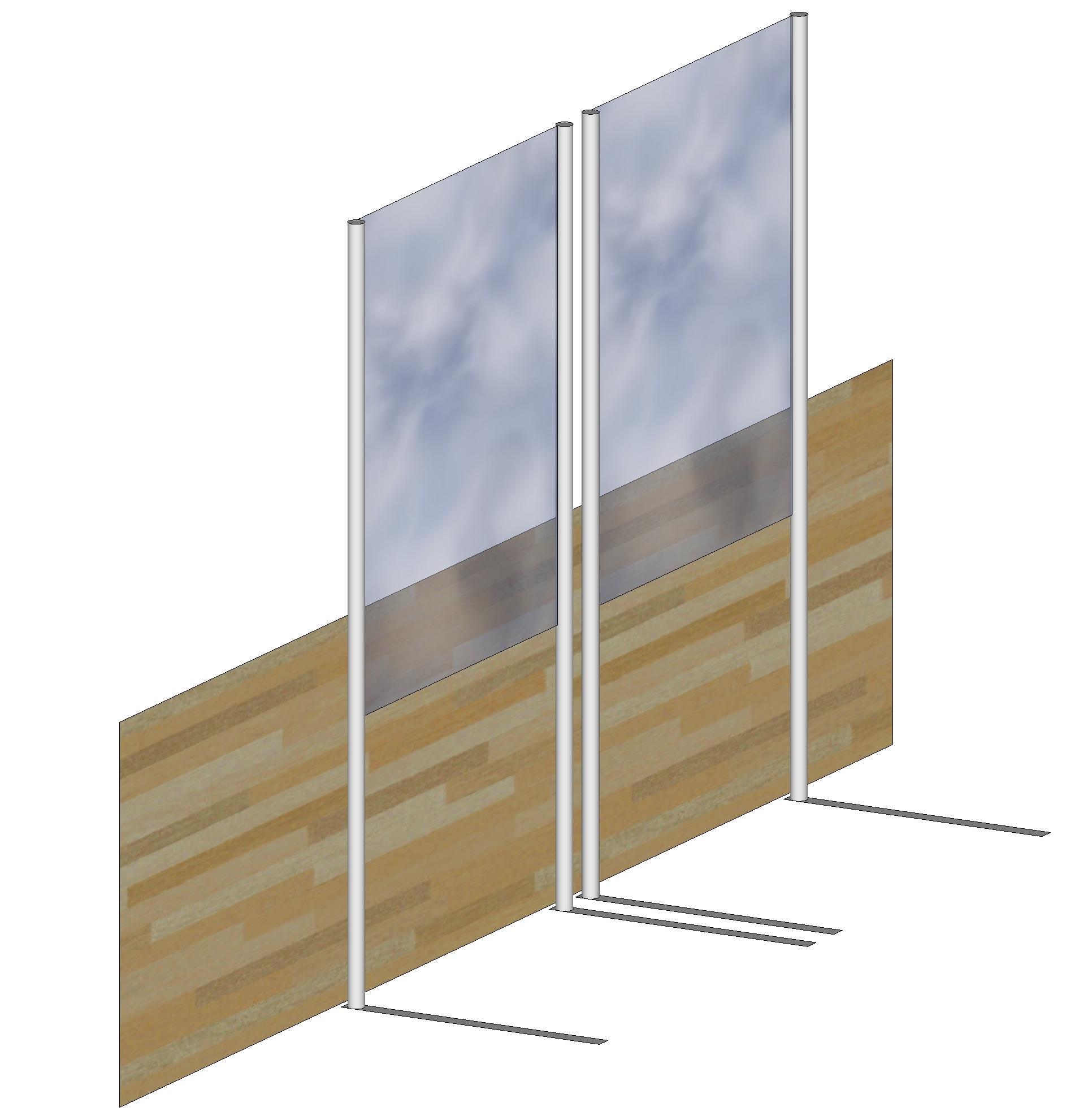
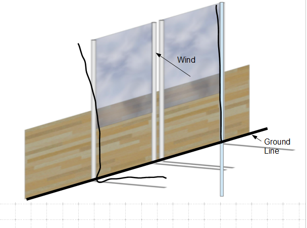
My idea is that each panel would be fixed to two supporting poles that are mounted on flat horizontal 'feet'. In this diagram, the wind would be directly onto the unprotected side of the fence, so the new panels are on the 'inside' of the fence:

enter image description here

Dimensions:

  • Height of existing fence: 1 m
  • Height from ground to base of perspex panel: 1 m
  • Height from ground to top of perspex panel: 2.75 m
  • Width of each panel: 1.4 m

-> Surface area of each panel: 2.45 $m^2$

Feet:

  • Made of iron (7.86 $g/m^3$) with cross-section 10 mm x 100 mm

-> Mass of each foot (per meter length): 1000 g/m

How long / heavy do those feet have to be to make the panels stable in a wind of (say) 6 m/s?

$\endgroup$
10
  • $\begingroup$ Are the new glass panels attached to the old (wooden?) fence. Also, is the wooden fence fixed to the ground separately from the glass panels? $\endgroup$
    – NMech
    Commented May 19, 2021 at 10:46
  • $\begingroup$ Hi @NMech. The wooden fence is separate and rigid. The panels are free-standing. $\endgroup$ Commented May 19, 2021 at 11:01
  • $\begingroup$ I'm guessing the perspex panels will be designated as temporary structures that you want to act like a fixed structures possibly because of municipal council regulatory requirements. I can't see the "feet" providing long term stable support. You would be better off getting some form of barrel or metal drum filling it with concrete and placing the support posts for the perspex panels in the concrete filled barrels. $\endgroup$
    – Fred
    Commented May 19, 2021 at 15:17
  • $\begingroup$ Hi @Fred. Actually, the idea is that the panels can be put in place only when we are using that area of the terrace, and wind speeds are sufficiently low... Since this is a roof terrace and the building's construction is rather lightweight, heave concrete weights are not really an option - they except the point-loading limits for the terrace. $\endgroup$ Commented May 19, 2021 at 15:39
  • $\begingroup$ Does the existing fence have sturdy posts that the taller posts for the perspex panels could be temporarily bolted to & secured to by large wing nuts? $\endgroup$
    – Fred
    Commented May 19, 2021 at 15:44

2 Answers 2

0
$\begingroup$

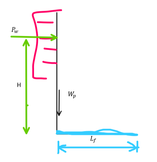
This is a side view of the panels
enter image description here

where:

  • $H$ is the height of the resultant concentrated wind force $P_W$ from the ground. Given the parameters of the problem, H should be equal to : $$ H= \frac{1+2.75}{2}= 1.875 [m]$$

  • $L_f$ is the total length of the horizontal part of the feet. The length of the feet will affect the weight, and the total weight of the feet $W_f$ will be equal to :

$$W_f = 2 L_F \cdot q\cdot g$$

where:

  • q is the mass per meter (1 kg/m)

  • g is the acceleration of gravity (~10 $m/s^2$)

  • 2 is because there are two (2) feet per stand therefore: $$W_f = 20 \frac{N}{m} L_f $$

  • $W_p$: is the weight of the vertical part of the panel (glass and metallic part). I will be assuming here that the weight is about 10 kg (i.e. 100 N).

  • $P_W$ is the total force of each panel (assuming that there is a uniform pressure on the panel (this is a semi valid assumption, but its simple enough to present here). This is the most involved part so I will break it up.

wind panel

In order to calculate the wind force on the panel:

The nominal wind pressure is $q_p$ $$q_n = \frac{1}{2} \rho v^2$$ where:

  • $\rho = 1.225[kg/m^3]$ is the air density
  • $v$ is the air velocity (6[m/s])

The wind pressure $q_p $ on the flat panel is $$q_p = C_d \cdot q_n = C_d \cdot \frac{1}{2} \rho v^2$$ where:

  • $C_d$: is the drag coefficient.

The total wind force $P_w$ on the panel is:

$$P_w= q_p \cdot A = A\cdot C_d \cdot \frac{1}{2} \rho v^2$$

Moment equilibrium.

If the wind blows in the direction of the initial image, then the panel will start to rotate/pivot around the rightmost part of the feet in the image (lets call that point A). In that case the moment equilibrium about A, will be:

$$\sum M_A = -P_w H + W_p \cdot L_f + P_f\cdot \frac{L_f}{2}$$

This need to be positive in order for the panel not to rotate about A. Therefore

$$\sum M_A \ge 0 \Rightarrow -P_w H + W_p \cdot L_f + P_f\cdot \frac{L_f}{2} \ge 0 $$

I will substitute the parameters that are depended on $L_f$:

$$-P_w H + W_p \cdot L_f + 20 \frac{N}{m} L_f \cdot \frac{L_f}{2} \ge 0 $$ $$ \frac{20 \frac{N}{m}}{2}L_f^2 + W_p \cdot L_f - P_w H \ge 0$$

You can then solve this equation and obtain two solutions. One will be positive and one will be negative. Values greater than the positive value, and values smaller than the negative value will satisfy the above requirement. (The negative value makes sense, because negative $L_f$, just means that the feet extend to the left).


Note that you should investigate also the other way overturning (wind blowing from the right.


another solution instead of really long feet.

Provided the existing fence has adequate structural capacity, you could try the following solution.

enter image description here

where:

  • red is the old fence
  • green are the new panels.
$\endgroup$
5
  • $\begingroup$ Hi @NMech. This is just what I needed, thank you. Thanks for the extra suggestion, too - although this whole problem comes about because the existing barrier cannot take an extra lateral or rotational load. I'll get calculating! $\endgroup$ Commented May 19, 2021 at 20:37
  • $\begingroup$ There is one more thing. The whole panel might translate before tipping over if the friction is not sufficient. So you need to consider that you have enough friction. $\endgroup$
    – NMech
    Commented May 19, 2021 at 21:29
  • $\begingroup$ Wind can blow from either side of the panel. In reverse, the pivot point is directly under the post, and the leg is lifting up losing contact with the soil. You should check how to tie the strap down for such a case too, or plan to rely on the existing wall as support? $\endgroup$
    – r13
    Commented May 20, 2021 at 0:24
  • $\begingroup$ @r13 please read the entire answer before commenting. I had already noted that. $\endgroup$
    – NMech
    Commented May 20, 2021 at 2:53
  • $\begingroup$ Is this the note "Note that you should investigate also the other way overturning (wind blowing from the right."? Well, the OP is satisfied with it, so no more comment here. $\endgroup$
    – r13
    Commented May 20, 2021 at 12:46
2
$\begingroup$

The proposed system won't work, as the foot straps are too flexible to prevent the large deflection and rotation of the posts. Instead, you shall embed the posts into the foundation (not shown) below the grade.

enter image description here

$\endgroup$
2
  • $\begingroup$ Hi @r13. Sadly this is not an option. As mentioned in the OP, I am searching for a free-standing solution. We can assume that the L-shape is rigid at the bend. It is clear that there does exist a length of foot which would allow the panels to resist the wind - the question is, how long would the feet have to be? I suspect that the answer will be something crazy like 3 metres, but there is such a number, surely? $\endgroup$ Commented May 19, 2021 at 17:37
  • $\begingroup$ The only free-standing (free to remove by hand) method is to weigh the post down with a chunk of concrete (with a hole in the middle) to counterbalance the wind force. Otherwise, you need to fasten the foot strap to the ground, then it is not free-standing. $\endgroup$
    – r13
    Commented May 19, 2021 at 20:05

Your Answer

By clicking “Post Your Answer”, you agree to our terms of service and acknowledge you have read our privacy policy.

Not the answer you're looking for? Browse other questions tagged or ask your own question.