0
$\begingroup$

I need some help with a statics design problem. I am tasked with designing a solar panel frame to mount on a building and am the only engineer on staff so I don't have anyone else to ask the simple dumb questions. Since I have no real experience doing wind load calculations I figured I would assume a load normal to the solar panel face. My idea is to use two square aluminum tubes mounted along the long side of the three solar panels stacked vertically along the tube. My analysis involves the support structure for one side, of one array column. As of right now I am hoping the solar panels themselves will suffice as cross-member connections. The details really don't matter, in fact the wind loading really doesn't matter either. It is the method I am having trouble with.

Want it to be able to withstand 125 MPH gusts. That appears to equate to 30 lbf/square foot. Given 18.47 sq. ft./ panel * 30PSF * 3 Panels + 135 lb panel wt = 1797 lbf. That's 1800 lbf total distributed load accross all three solar panels in one array column. Since there will be two support structures per array column that's 900 lbf distributed load per support structure or 4.48 lbf/inch. (Not sure where I got 6.2 on my drawing)

I know I need to determine the reactions at each pin joint, do shear and moment diagrams and then I will do a buckling failure analysis on each support strut member. Any guidance would be appreciated, started doing some calcs on my own and things just weren't coming out right.

enter image description here

$\endgroup$

2 Answers 2

0
$\begingroup$

Often times your assumptions make a bigger difference than the rigor of your mathematical analysis. Remember you should select assumptions that favor an easier analysis.

Also remember that the guys your hire/employ to make a simple structure like this are not going to measure things to the .1 degrees; their tools don't even support that. These are probably pinned connections, so only lengths are needed, but keep that in mind and leave those numbers off the mfg print.

Don't put your structure right up to the corner of the building; give yourself a standoff. If there are any errors in length they will not be easily corrected.

Not sure if your location has snow, but often times snow load will be greater than wind load. Wind loads are horizontal except when around other structures like in your situation. The two highest loads left to right and right to left could actually be lifting the panels up due to the captured air pocket; so look at that scenario also.

Having built solar hot water and solar PV mounts, I do not recommend using the panels to hold square or take any load between the other supports. The structure should bear all the load and the panels should be attached per the manufacturer recommended method (that also covers you if they do break).

If it were my design, I would select a large enough primary beam (201") such that it can handle the chosen load with just two supports. One at a standoff, say 6" up from corner of the building, and another selected such that it is a symmetrical connection point based on your desired mounting configuration. Basically the only optimization you have to do is figuring out the amount of cantilever to amount of span. Simple designs are easier to calculate, easier to optimize without a computer, and easier to manufacture. Unless you need to split hairs for low mass designs like in aerospace, your materials are much much cheaper than labor.

If you still wish to solve your design and assumptions as is, I would rotate the whole system mathematically so that the distributed load is either in just x or y. That gives you load components that are either in just x or y. Then use the angle of each member to compute the total load on each.

$\endgroup$
1
  • 1
    $\begingroup$ Thank you for the advice! I should mention, I was asked to design a framework that could be installed by two or three people so I was attempting to make it as light as possible. Hence the aluminum tubes and the desire to make it only just strong enough rather than throw big steel at the problem. Your comments were helpful though! $\endgroup$
    – Jason P
    Commented Aug 14, 2018 at 13:19
0
$\begingroup$

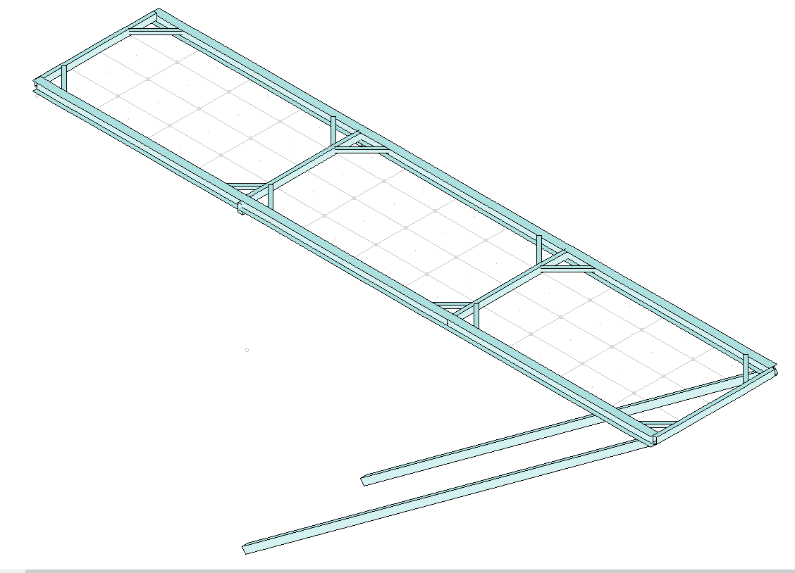
Just FYI I was able to solve my design using RISA 3D. This is an excellent software! Ended up designing for a 125 MPH / 40 PSF wind load. Tested the frame in both horizontal and 50 degrees from horizontal orientations. Test loads were applied normal to the panel face and parallel to the ground in two different scenario groups. Loads were applied downward on all panels at 40 PSF, upward on all panels at 40 PSF, combination load: upward on the top panel / downward on the two lower panels, and the reverse of that combination load.

For the moment I am neglecting snow loads based on the fact that as you move north the required solar panel tilt angle becomes greater up to about 45 degree slope. And where the solar panel array would be most vulnerable (near horizontal) is in regions with zero snow load. But I will have to revisit this topic later.

Ended up using 6061-T6 3x2.03 I-beams for the long side members. Was even able to eliminate two support struts in this configuration.

Vortex shedding may be a problem however depending on how the assembly of frames is arranged. Structure frequency is 7 to 77 Hz for the first five modes. Based on the Strouhal number vortex shedding frequencies could range from 11 to 26 Hz. However when I analyze the shedding frequency across the assembly of all six planned frames the range drops to 2.2 to 2.7 Hz. Some type of vortex suppression devices may be required on the long struts.

enter image description here

$\endgroup$

Your Answer

By clicking “Post Your Answer”, you agree to our terms of service and acknowledge you have read our privacy policy.

Not the answer you're looking for? Browse other questions tagged or ask your own question.