0
$\begingroup$

I need a little help with SolidWorks.

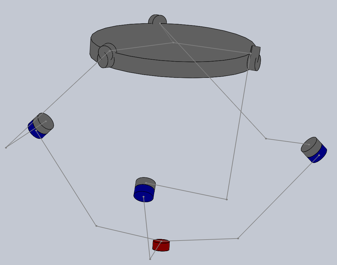
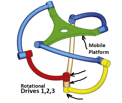
I need to assemble such a mechanism, which I am currently working on.

But I get a rather complicated and cumbersome algorithm:

  1. First, I build a "wireframe" from the necessary lines and other connections.
  2. Then I build cylinders for rotary articulations. 2. Then inside them I build auxiliary surfaces, place circles on them and build a circular arc with their help.
  3. I do the same with other arcs.
  4. I build the platform separately. it is impossible to do everything in one picture.

Maybe a more experienced person can tell me how I can build such a mechanism in a simpler way?

I would be glad and grateful for your help.

enter image description here

https://www.youtube.com/watch?v=kN09M5QGGBk

$\endgroup$
8
  • 1
    $\begingroup$ It's a rather complicated and cumbersome device. And I think you are complicating it by having different blue arms (left one is different from other 2). Video has same blue arms and the upper connections for the base arms are all the same. Only true difference is the extensions of lower connections of base arms to allow for interconnections. That may change how green platform moves. $\endgroup$ Commented Jul 14, 2021 at 17:57
  • 1
    $\begingroup$ I'd build the green platform. I'd build upper and lower arm as two, identical, physically unconnected, cylinders. Put it in assembly and change arm models to get the motion correct. Then worry about physical interconnections in the models and making 3 different lower arm models. Then I would think about an algorithm. $\endgroup$ Commented Jul 14, 2021 at 18:08
  • 1
    $\begingroup$ What version of SW are you using? $\endgroup$ Commented Jul 15, 2021 at 10:27
  • 1
    $\begingroup$ See my comment reply to engineering.stackexchange.com/questions/44920/… - you have the same sort of problem. Make a skeleton sketch, make your parts in a rigid configuration, and then make flexible by suppressing mates. $\endgroup$ Commented Jul 15, 2021 at 10:40
  • 1
    $\begingroup$ @JonathanRSwift In my institute there is an opportunity to work in SW 2020. You can show the CAD-model you want. $\endgroup$
    – ayr
    Commented Jul 19, 2021 at 9:24

1 Answer 1

1
$\begingroup$

enter image description here

I tend to use SolidWorks assembly to trial and error these types of assemblies, then worry about how to make it work. Constrain (Angle and Distance) the crap put of components to start and remove them as components are interconnected.

Following the process I outlines in the comments:

Platform: 100mm.

Upper Arm: 105mm by 50mm, Angle 90°. The dimensions you will have to tweak at some point. Your algorithms. I started with 100mm by 50mm and it's not perfect.

Lower Arm: 50mm by 50mm, Angle 45°.

Mate all the lower faces. Place an angle mate of 120° on each of the lower arms. The angle mates will allow you to construct the mechanism. Mate faces to top plane.

Mate one of the lower arm origins to the assembly origin. Origin must be on mated faces.

Mate Upper Arms to Lower Arms. Place an angle mate of 90° on upper arm to lower arm. Make sure all upper arms are in the same direction.

Mate platform to upper arms. You can see I cheated and mated them to a point.

It's a rather complicated and cumbersome device, but this will get you going in the right direction. Remove all angle mates and you should have the basic mechanics.

Once you get that working, upper arm is identical, but lower connection cannot be in the same place, so bottom 1 will be at 50mm by 50mm at 45°. Next 60mm by 40mm at 45°. Last at 70mm by 30mm at 45°. The actual numbers will depend on your actual dimensions.

This has been solved on the web with 3D printed files 3D Print Timelapse Build: Spherical Parallel Manipulator.

Thingiverse project.
$\endgroup$
6
  • $\begingroup$ Thank you for your answer! Oh no, it's a crap :)) ibb.co/MDRwYYz I will try to fight this. $\endgroup$
    – ayr
    Commented Jul 15, 2021 at 9:12
  • 1
    $\begingroup$ The link and thinkiverse link works. Not sure your problem. $\endgroup$ Commented Jul 15, 2021 at 9:16
  • $\begingroup$ I have another question. Here you have provided a link to the solidwork manipulator model. Tell me, can these parts be resized? Change the angle of the arc, the dimensions of the parts themselves, etc. ? If so, that would be great. $\endgroup$
    – ayr
    Commented Jul 15, 2021 at 9:54
  • 1
    $\begingroup$ I have an educational copy, so I can't do that. $\endgroup$ Commented Jul 15, 2021 at 12:07
  • $\begingroup$ Is it possible in principle for these files? $\endgroup$
    – ayr
    Commented Jul 15, 2021 at 12:09

Your Answer

By clicking “Post Your Answer”, you agree to our terms of service and acknowledge you have read our privacy policy.

Not the answer you're looking for? Browse other questions tagged or ask your own question.