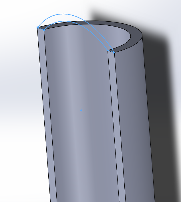
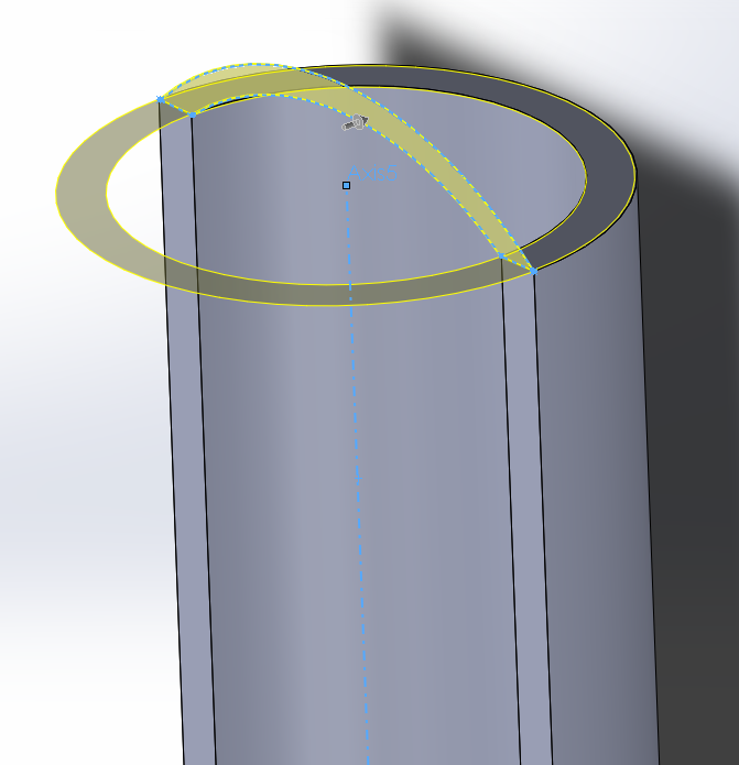
Whenever you are sketching a profile to be revolved in any CAD package, you should start by drawing your axis of revolution into that sketch as a construction line. Then, keep every other line to one side of that axis. In SolidWorks, this gives you the added benefit of being able to dimension diameters, rather than radii, which may be more appropriate. I've shown a 'best practice' sketch below, showing how you can generate the object you're looking for, with just four dimensions, and one revolve feature in the tree. Simply revolve this profile by 180°
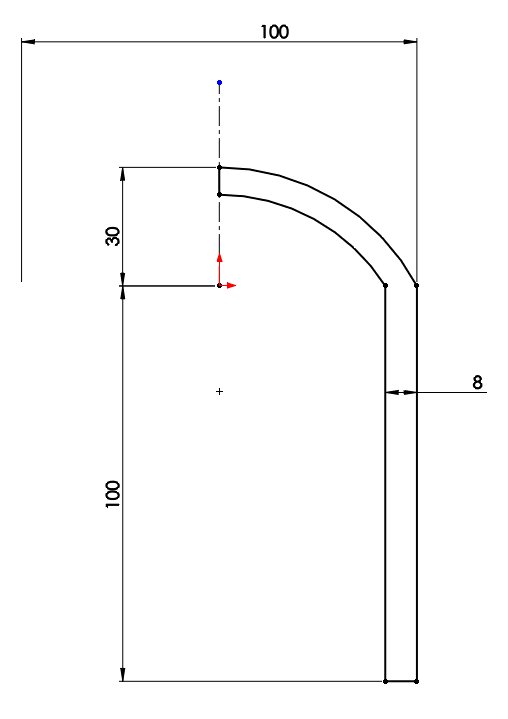
That said, there are of course several other ways to generate the 'half dome', which you are after. I'll go through one of these below. Please note that this is not recommended in this situation but I've included it to give an idea of how to use the tools involved more generally, and to show how many options are present in all situations.
The original question included a question on how to define the axis. If you wanted to revolve your dome in the other direction, then you need to create a 'master' sketch to not only define the axis, but also the plane on which the sketch should be created.
Start by extruding the half-cylinder:
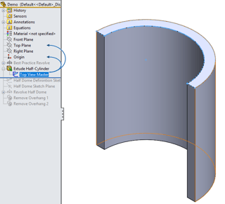
Then on the Right Plane, create a master sketch, which defines the shape of the dome that you would like. This should only contain one driving dimension, You should also add driven dimensions that show the radius of the dome, and the angle of the revolve to come
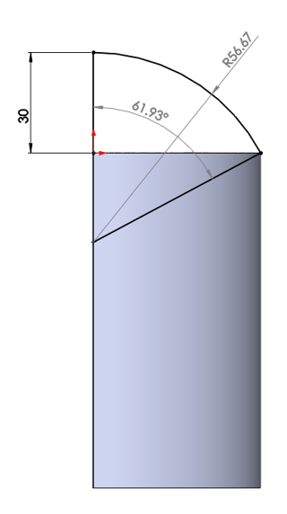
Now define a new plane for your sketch. It needs to intersect the centerpoint of the arc in your master sketch. I used the line from that sketch (coincident) and the Right Plane (perpendicular) as my references
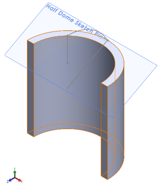
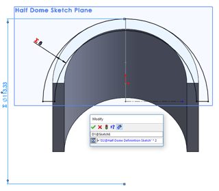
Now, start your sketch for the dome on the new plane. All the dimensions in this sketch should be equation driven, since you've already defined all the geometry elsewhere. Again, remember to put a centreline into your sketch and keep everything else on one side of it. The diameter of the circle should be twice the radius you measured in the master sketch, and the thickness should be equal to that set in your original extrude sketch. This means that if you ever wish to modify the height of the dome, or the diameter of the tube etc., this sketch will automatically rebuild to the correct dimensions.
Now you are ready to revolve your dome. Use the angle dimension from your master sketch to define the revolve angle
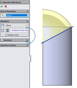
You will now be left with a shape which is correct on the inside, but has some undesired overhangs on the outside.
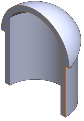
In this case, you could simply run a cut-extrude around the outside, but another way to achieve this (in the spirit of explaining more complex tools for future use) is the 'delete face' tool. Simply delete the face underneath the overhang, with "delete and patch" selected, and SolidWorks will extend the Cylinder face up to meet the dome. You will have to do this once for each overhang. Deleting both at once will not work due to the way both overhang faces meet at a single vertex causing the maths to fall over.
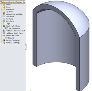
The part has now been completed, and is dimensionally identical to what was achieved with a single revolve previously.
The fundamental concept of master modelling (defining geometry in a sketch that isn't actually used to build the model, and referring to that using equations in order to allow automatic updating of the built geometry) is extremely powerful, however, and in other more complicated examples, it is absolutely the best way to work.
