0
$\begingroup$

Spherical Parallel Manipulator in SolidWorks

I am drawing in SolidWorks a 3D arc with two holes on the edges. An axis of rotation passes through the center of one of these holes, around which the arc rotates according to an arbitrary law.

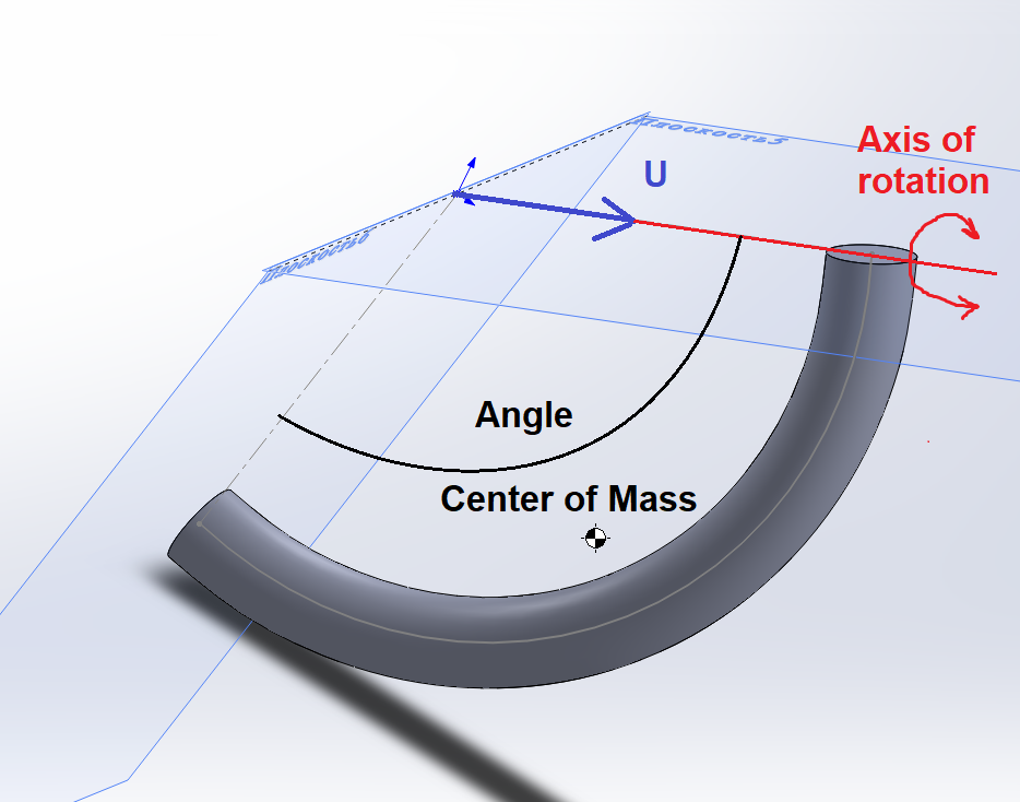
I want to learn how to display nice and informative reference geometry. In this case, I need to depict: the axis of rotation, a vector (for example, U) co-directional with it, the center of mass, etc. Something like this:

enter image description here

How is it done in SolidWorks?

$\endgroup$
5
  • $\begingroup$ Any arc is actually 2d its just a question of finding the plane. in this case you design them flat and assemble in position $\endgroup$
    – joojaa
    Commented Dec 29, 2022 at 9:02
  • $\begingroup$ @joojaa It was a sketch of the future design. I now have progress and have updated the question. Now I know how to add the centers of mass, but how to display its coordinates, the angular size of the arc, the axis of rotation and its direction? How to draw it? $\endgroup$
    – ayr
    Commented Dec 29, 2022 at 10:16
  • $\begingroup$ the center of mass is a function of geometry. So you need to have something that offsets the weight then run the shapes dimensions to optimizer that tries to minimize target minus real COM. $\endgroup$
    – joojaa
    Commented Dec 29, 2022 at 13:17
  • $\begingroup$ @joojaa Yes, these are subtleties of calculations. But I'm interested in something else: I need SolidWorks functionality in a beautiful display of the details I specified (I need this for publication). Otherwise, everything has to be redrawn in LaTeX. $\endgroup$
    – ayr
    Commented Dec 29, 2022 at 16:52
  • $\begingroup$ Make a drawing. $\endgroup$
    – joojaa
    Commented Dec 29, 2022 at 17:05

1 Answer 1

1
$\begingroup$

I'm assuming you want to display these things in the part editor?

If you make sketches (2D or 3D) with these lines, arcs and points, you can just leave them in your part and they'll be displayed while you work.

One caveat, there will be no labels. I have solidworks 2016, and maybe it's better in the future versions, but I find that adding annotations inside sketches does not work well. I wouldn't bother.

If I really needed a label I might insert some text in the sketch (as you would do for engraving), not elegant but it might work ok.

As far as I know you can't dimension to the center of mass, but you can show the coordinates, or a crude and simple way to locate relative to your part would be to zoom way in and place a point on it.

The editor isn't really designed to create illustrations, so although I think you'll be able to come up with something workable, I likely will not be "beautiful" without some post processing in GIMP or similar.

Crude example: example of adding reference sketches to part
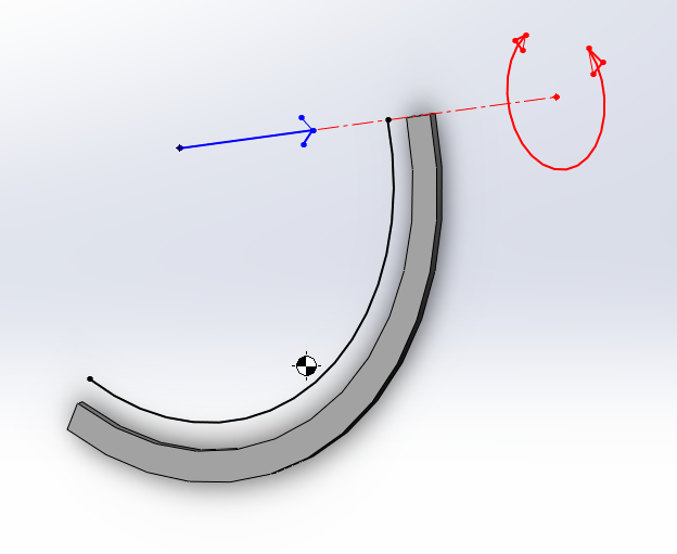
If I wanted this to look nicer I would draw the arrows on the ends of the lines by hand, and add labels. That should look decent.
$\endgroup$
1
  • $\begingroup$ Thank you for your answer! I worked a little more in SW and realized that simple geometry can be drawn quite quickly with my own hand. And this is enough for now. I accept your answer. $\endgroup$
    – ayr
    Commented Jan 26, 2023 at 4:29

Your Answer

By clicking “Post Your Answer”, you agree to our terms of service and acknowledge you have read our privacy policy.

Not the answer you're looking for? Browse other questions tagged or ask your own question.