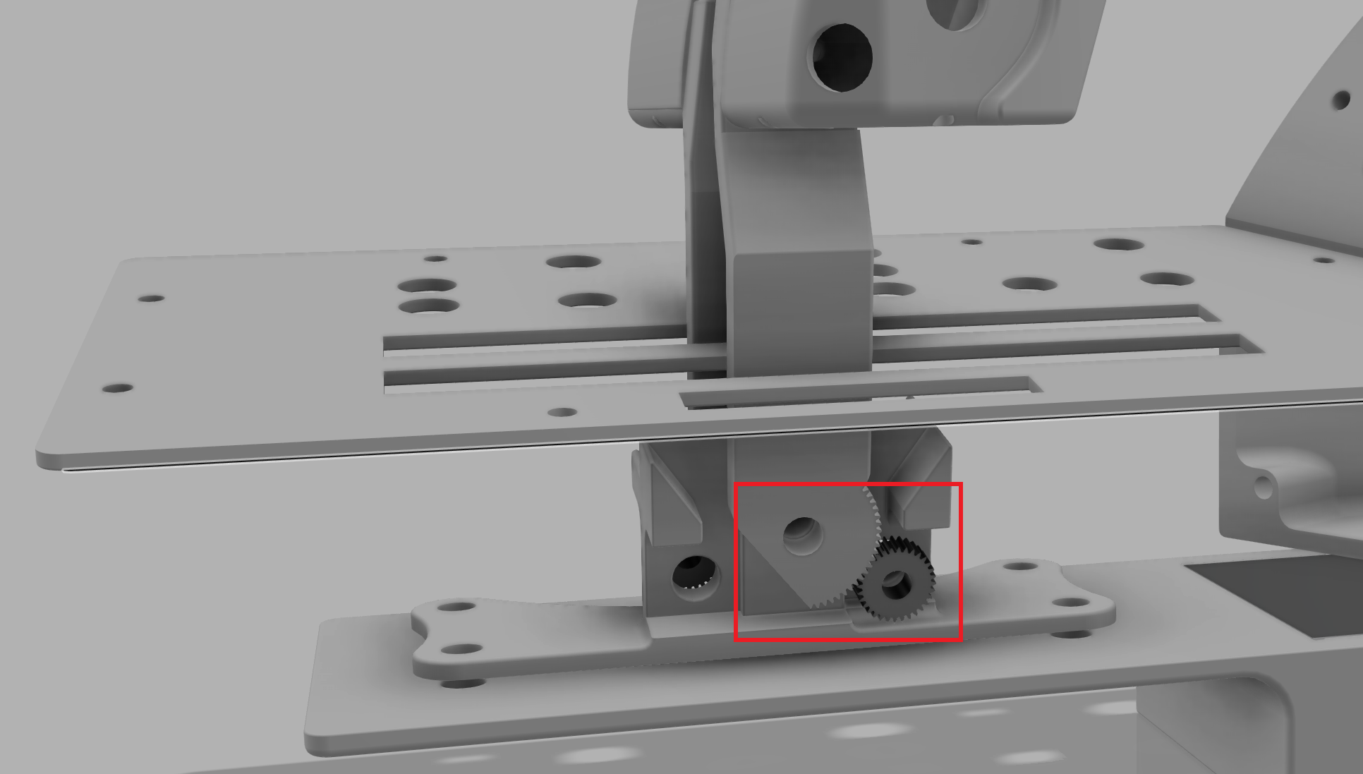
I'm 3D printing an aircraft throttle unit as a POC and am trying to calculate the gearing ratios that are required in order transfer the full range of linear motion into a directionally opposed sensor whilst being constrained by certain design factors.
In the attached image, each throttle unit (L&R) will have a total articulation of 70° (35° each way from centre) and I'm trying to work out how to transfer/translate that linear motion into a rotational force that'll drive input into a potentiometer with a rotational constraint of 295°
I've tried calculating the ratio myself using the following expression 'm=a/r' where 'm' is equal to the articulation of linear motion divided by rotational constraint to gives me 1:4.2 but I have a feeling that's incorrect.
Also, once I have the correct gear ratio I'm unsure of how to work out the number of teeth required on both the spur gear and drive gear (is it as simple as for each tooth on the drive gear, 4 (rounding down) are required on the spur gear?)
Thanks in advance!
