1
$\begingroup$

Updated with comments/answers from community to make more complete

I'm trying to understand why gears are designed in some specific way instead of another. So far my understanding is that:

  • energy is preserved (- some loss due to friction)
  • if the speed of rotation is changed
  • then the force/torque is inversely & proportionally changed

Criteria I'm aware of are:

  • speed: how much to increase/decrease
  • force/torque: how much to decrease/increase
  • backlash: lost motion due to gap between gear teeth which can cause precision issues
  • robustness of gears: strong enough to handle increased torque?
  • angle of rotation: eg change 90 with worm gears
  • direction of rotation: whether we want input/output rotate in same direction
  • wear and tear: due to contact/force applied by gears on each other
  • space available: to fit the gears

And some business criteria such as cost & availability of the parts.


QUESTIONS:

-Other than those listed above, are there any other considerations when designing gears?

More specifically, if space,cost,availability weren't concerns, would there be any reason why someone would favor a design with fewer gears (eg A) rather than more (eg B)?

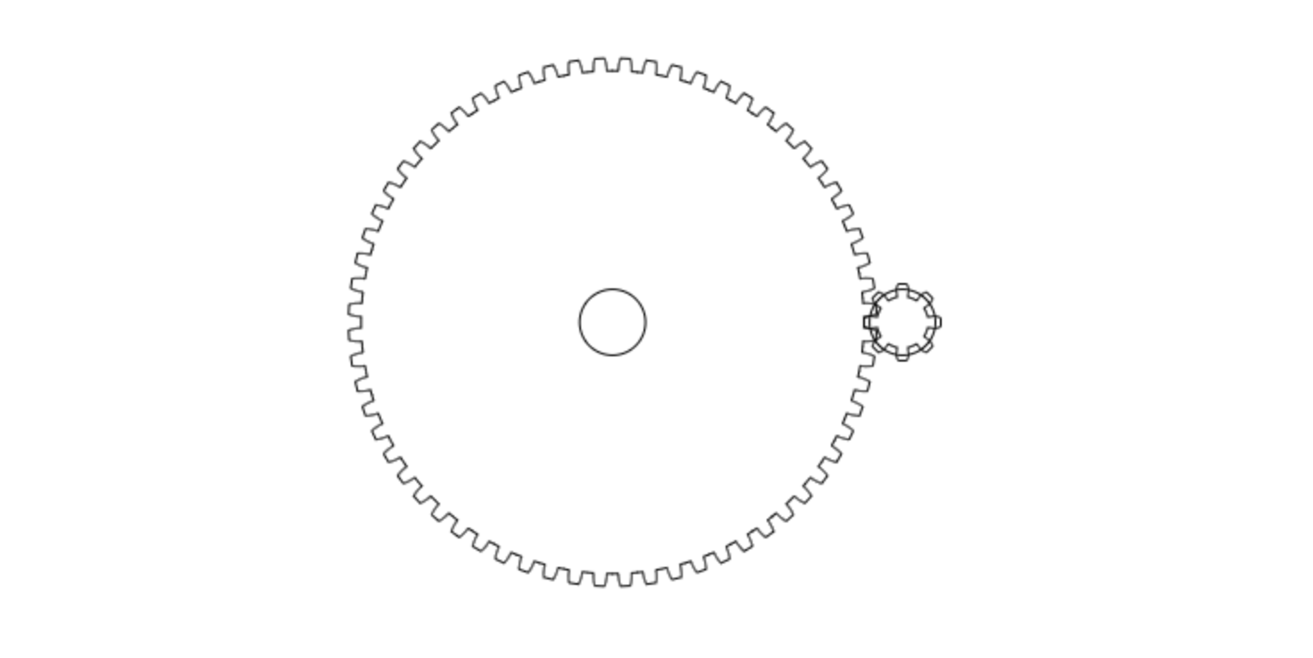
A: 8:1 ratio with 2 gears (64 teeth -> 8 teeth):

enter image description here

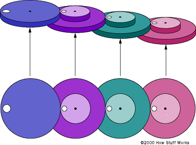
B: Same 8:1 ratio with 4 gears (2:1 ratio on the 3 driven gears, taken from here)
enter image description here

$\endgroup$
3
  • 1
    $\begingroup$ You haven't mentioned backlash? $\endgroup$ Commented Mar 27, 2021 at 12:48
  • 1
    $\begingroup$ While overall speeds, forces and torques are important for the system, these flow down into forces seen on the gears themselves. Take a look at pressure angles, imbalances on the system (gears are not often symmetrically loaded and wear from turning is similar to repeatedly bending your shafts), and friction at the contact surfaces of gears. $\endgroup$
    – Abel
    Commented Mar 27, 2021 at 13:33
  • 1
    $\begingroup$ Direction of rotation. Whether you want input and output rotating in same direction. $\endgroup$ Commented Mar 27, 2021 at 15:50

2 Answers 2

3
$\begingroup$

I think you've most criteria covered for the case you are considering in your post. The only criterion I haven't seen is wear and tear.

Regarding wear and tear there are mainly the following considerations:

  • the first is that the smaller gear should not have less than 11 teeth under any circumstances (preferably not less that 14 if possible). Usually 17 teeth is the starting point for a small gear. This is to avoid undercutting.

enter image description here

  • the other is that in order to have uniform wear on the teeth, you should have gears with teeth $z_1$ and $z_2$, where the greatest common denominator is 1. (however this is debatable by some that actually advocate exactly the opposite)

All the above considerations are important in choosing the most appropriate gear set.

In general the main drawbacks of having multiple stage gears (4 gears of 2:1) is the space required, the cost, and alignment. Apart from that in terms of wear and tear, the multiple stages offer significant opportunities (gradual increase of forces, and different pitch diameter/ module - depending on whether you use Imperial or SI).

$\endgroup$
2
  • $\begingroup$ What do teeth z1 and z2 refer to? $\endgroup$
    – Max
    Commented Mar 28, 2021 at 6:34
  • $\begingroup$ $z_1$ and $z_2$ is a standard notation where I come from for the number of teeth on gear 1 and gear 2. Usually gear 1 has the least number of teeth/diameter. $\endgroup$
    – NMech
    Commented Mar 28, 2021 at 7:17
1
$\begingroup$

It really depends on what your application requires. Sometimes the optimal layout isn't feasible so you have to use what is. But here are some general rules of thumb to add on to NMech's answer:

  • Typical maximum ratio is 5:1 or less for parallel axis spur gears. If your gear radius of curvature is significantly greater than your pinion, you'll have significant sliding tooth stress as the gear teeth come in and go out of mesh. This will wear your teeth faster. This might also dictate what lubrication you need if the contact pressure is high enough. Lubrication breakdown is the main cause of machine failure.
  • Minimum number of teeth in your pinion (smaller gear) for 20 degree pressure angle gears (the most common angle for off the shelf parts & tooling) is technically 24 to avoid undercutting.
  • A larger diameter output gear will have higher inertia acting as a flywheel. If you want to tightly control position or are making frequent changes in direction this could be an issue. Conversely if this is running for long periods at the same speed this might be desired.
  • The more gears you have will require more hardware to mount the shafts rigidly, more precise shaft locations and increased labor during assembly. In general, more things that can ultimately break down and fail prematurely.
  • By definition you will have more backlash in a train with more gears, as you need to account for some runout and thermal expansion in each mesh to avoid binding. This will limit your shaft positional tolerances and gear runout. If they become too tight it may just be impossible to manufacture what you need.
  • With more gears you can achieve a more precise ratio without losing bending/wear resistance. For 2 gears having an exact 8:1 ratio the same tooth on the pinion will always mesh with the same teeth on the gear. To work around this you would need something like 7.96:1 or 8.04:1. With multiple gear meshes you can achieve 8:1 exactly and still have even tooth wear.
  • You'll have more losses due to friction for more gears. Spur gear meshes are about 98% efficient at a maximum. On a small scale that might not mean much but if you have several of these running 24/7 those losses start to add up.
  • Noise. More gears in mesh = more noise. Depending on the environment you may need to limit the noise of the gear train/machinery for OSHA, local ordinances, etc.
  • Available center distance. With layout A you are locked where your input to the pinion and output from the gear can be located. With layout B the centers of rotation do not all need to be in line, you could conceivably fit them in a much smaller footprint.

There are more but without a few concrete parameters it's mostly just rules of thumb.

$\endgroup$
2
  • $\begingroup$ Wow. Thanks so much. Need some time to process it all, might come back with a few points reworded just to ensure I understand them fully $\endgroup$
    – Max
    Commented Mar 29, 2021 at 15:52
  • $\begingroup$ Yeah. There are probably hundreds of gear design textbooks and thousands of pages of ISO/US design standards. Little difficult to encapsulate everything into a single SE post. $\endgroup$
    – jko
    Commented Mar 29, 2021 at 16:38

Your Answer

By clicking “Post Your Answer”, you agree to our terms of service and acknowledge you have read our privacy policy.

Not the answer you're looking for? Browse other questions tagged or ask your own question.