1
$\begingroup$

The problem : I need to create a mechanism with 2 parallel shafts, at some distance apart, rotating in the same direction, either clock- or anticlock-wise.

The distance (> 1m) makes it impractical to set a chain of gears between the shafts, so my approach is to have a third shaft at 90 degrees with bevel gears; the driving motor could attach to this third shaft. It has been pointed out to me that a pulley-belt approach could also be used, but the distance between the parallel shafts makes me prefer the 90-degree shaft approach.

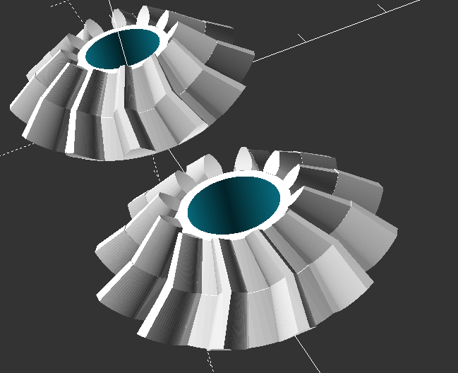
Not being a mechanical engineer, I tried to understand a bit more about bevel gears, and found out there are straight, spiral and other types. The 3D library I'm currently using for generating the gears creates angled teeth.

bevel gears with angled teeth

So here's the 1st question : for any type of bevel gear except the straight ones, does the geometry of the teeth have any impact on the direction of rotation ?

Since I don't want different rotation speeds on the parallel shafts, and there is no constraint on the rotation speed of the third, 90-degree shaft, so far my plan is to create gears with identical sizes (number of teeth).

And here comes the 2nd question : Should I use larger or smaller gears ? What's the impact of the number of teeth on the gear operation for the bevel gears ?

As a side note, I plan to 3d-print these gears for the prototype, so any comment that can factor this in is highly appreciated.

Thank you all in advance.
$\endgroup$
8
  • $\begingroup$ What range of rpm are you working with? $\endgroup$
    – Solar Mike
    Commented May 21, 2019 at 15:20
  • $\begingroup$ Howabout 2 U-joints instead $\endgroup$
    – joojaa
    Commented May 21, 2019 at 20:14
  • $\begingroup$ @SolarMike Somewhere between 200 and 400 rpm. Right now, I'm waiting for the motors, but I've tested a first prototype with a 300-rpm screwdriver. $\endgroup$
    – stefanu
    Commented May 22, 2019 at 4:45
  • $\begingroup$ @joojaa you mean two at 45 degrees ? I didn't think of this before since I'm 3D printing the prototype and I'm not sure the joints can be strong enough. $\endgroup$
    – stefanu
    Commented May 22, 2019 at 4:48
  • $\begingroup$ AS you now mention "strong enough" what is the load you have to support? Are there any shock loads? Please update your question with relevant information and don't leave it in the comments. $\endgroup$
    – Solar Mike
    Commented May 22, 2019 at 4:54

1 Answer 1

1
$\begingroup$

For your selection of gear models to test via 3D printer, consider a convenient search for "openscad bevel gears" as your starting point. You will find quite a few creators of the code that can be customized to meet your specific requirements. The creators will often provide "canned" or "out-of-the-box" models that may also fit your objective.

You ask about the number of teeth for the gears. From a layman's point of view, more teeth means less wear, longer life and smaller loads per tooth. A bevel gear will have substantial mesh surface which, with a larger diameter, means the forces are better spread along the radius.

$\endgroup$
3
  • $\begingroup$ Thank you for the explanation. As I understand it, I should use the largest possible number of teeth, limited by the overall available space where the gears will sit. $\endgroup$
    – stefanu
    Commented May 22, 2019 at 4:51
  • $\begingroup$ As for the library, I'm 'playing' with this one : link. That's the one I used in the image. $\endgroup$
    – stefanu
    Commented May 22, 2019 at 4:52
  • $\begingroup$ A large gear is good. If 3D printed (assuming FDM) you may have better results with fewer larger teeth than a metal equivalent (at the same diameter) $\endgroup$ Commented May 22, 2019 at 6:21

Your Answer

By clicking “Post Your Answer”, you agree to our terms of service and acknowledge you have read our privacy policy.

Not the answer you're looking for? Browse other questions tagged or ask your own question.