2
$\begingroup$

How do you create a state space representation of the following input/output equation:

$$ \dot{y} = -ky + u + a\sin(ωt) $$

where the parameters $k$, $a$, and $ω$ are unknown.

The end goal is to create a model reference adaptive controller (MRAC) using only the measurements of the input and output of the system. I believe the first step of this process is to create a state space model for the system from the equation given above. Without the addition of $a\sin(ωt)$ this would be a simple problem but that additional sine term is throwing off my calculation.
$\endgroup$
4
  • $\begingroup$ The term $α\sin(ωt)$ is not a constant. You just need to study how to design a MRAC for time varying systems I guess. $\endgroup$ Commented Apr 29, 2020 at 21:49
  • $\begingroup$ I meant it is not a function of U or Y. Care to explain further? $\endgroup$
    – Kyle Macke
    Commented Apr 29, 2020 at 22:06
  • 1
    $\begingroup$ I would but it is all about theory which you can find in many textbooks and online sources. The concept of the forum is to post what you have tried, state the problems you are facing and then we could help you. Just providing the solution to a homework-based question is like copy-paste for you. $\endgroup$ Commented Apr 29, 2020 at 22:11
  • 1
    $\begingroup$ Why don't you create an inputless state space model that generates a sinusoid? $\endgroup$ Commented May 1, 2020 at 18:24

1 Answer 1

3
$\begingroup$

You can switch to the frequency domain to look at the transfer function of the system. For you particular case, taking the Laplace transform of both sides gives

$$ sY(s) = -kY(s) + U(s) + \frac{a\omega^2}{s^2+\omega^2}, $$ or

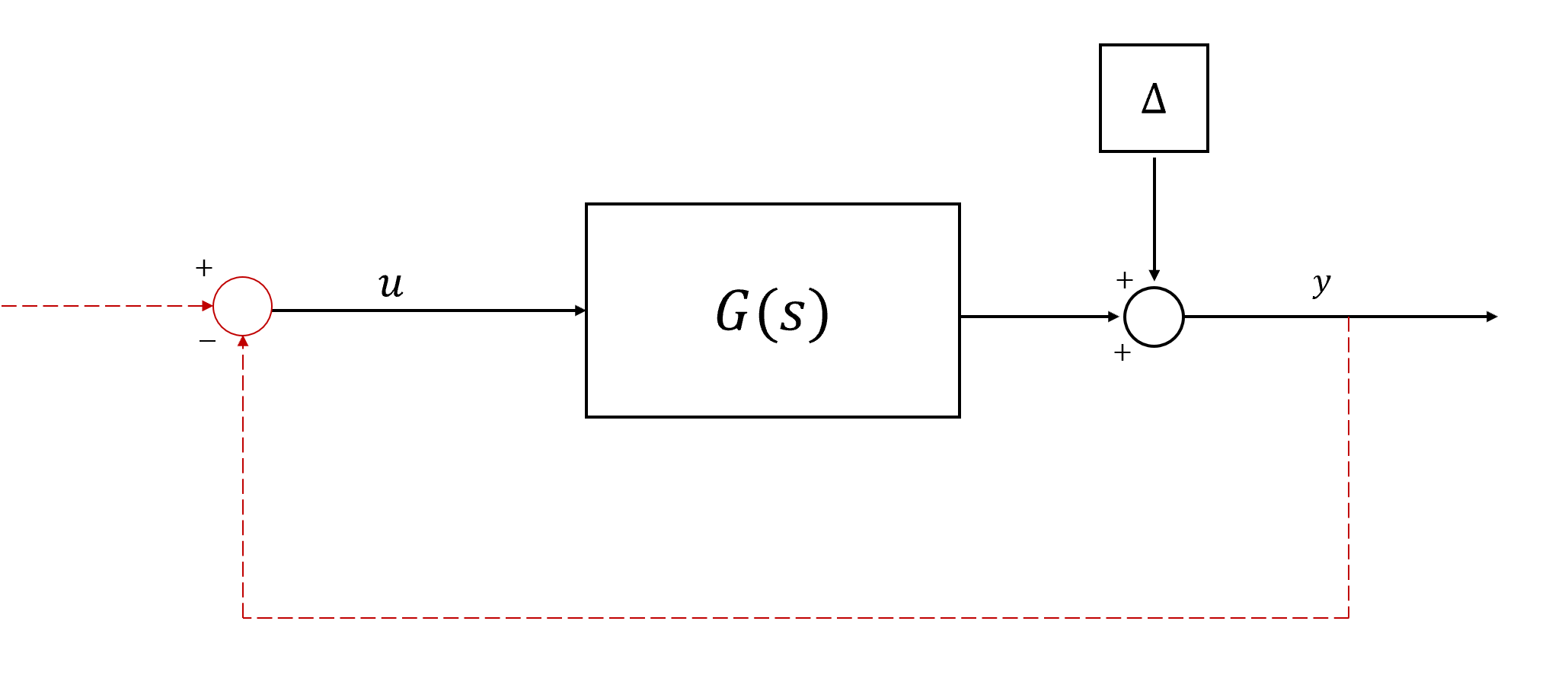
$$ Y(s) = G(s) U(s) + \Delta(s) = \frac{1}{s+k}U(s) + \frac{a\omega^2}{(s^2+\omega^2)(s+k)}. $$

To me, this looks like a linear system with some output disturbance. To get the state space from $G(s)$, note that the transfer function of a linear SISO system is given as

$$ G(s) = c(s - a)^{-1}b + d, $$ so one possible realization is

$$ \dot{x} = -kx + u, \qquad \bar{y} = x, $$ and it follows that the true output $y = \bar{y} + a\sin(\omega t)$. A block diagram of the system is shown below. From there, you can implement any particular controller you're trying to design (either open loop or closed loop).

Block Diagram

$\endgroup$
2
  • $\begingroup$ One could incorporate the sinunoisal signal into the system. $\endgroup$ Commented May 1, 2020 at 10:42
  • $\begingroup$ I am still trying to understand why you added the (filtered) sinusoidal "disturbance" to the output rather than to the input. Note that $\Delta$ could be replaced by the cascade of a sinusoidal oscillator and $G$ itself. So, you have the block $G$ twice. $\endgroup$ Commented May 2, 2020 at 3:40

Your Answer

By clicking “Post Your Answer”, you agree to our terms of service and acknowledge you have read our privacy policy.

Not the answer you're looking for? Browse other questions tagged or ask your own question.