4
$\begingroup$

Inspired by this question, and also this answer to a separate question.

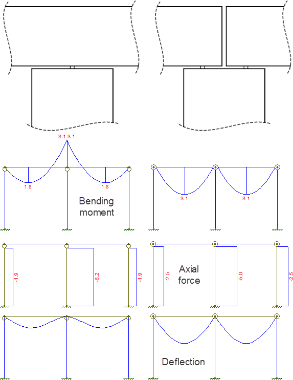
I have two beam models, one with two independent spans (a full hinge), another is a continuous beam over both spans (only column is hinged), the below is the diagram of both beams, and their force/bending moment distribution:

enter image description here

How can I derive from first principles of static analysis or from rules of thumb that continuous beams have a smaller deflection?

$\endgroup$
3
  • $\begingroup$ my understanding is that solid mechanics as such can not be derived from first principles without adding a corrective magic constants here and there, to account for uncertainty of how materials actually behave. Most of the calculations are not derived from first principles but trough empiric measurements and reasoning on top of those. $\endgroup$
    – joojaa
    Commented May 28, 2016 at 10:28
  • $\begingroup$ @joojaa, I've updated the question to accept any reasoning from rule of thumb $\endgroup$
    – Graviton
    Commented May 28, 2016 at 14:13
  • $\begingroup$ Well no i just meant that having calculation based on first principles means that they can be derived to central atomic things of physics. But solid mechanics is not derived that way they are engineering maths that have been empirically built from measurements to be a model for engineering. They do not derive from first principles but are very accurate maths in their own right still despite of this. $\endgroup$
    – joojaa
    Commented May 28, 2016 at 14:22

3 Answers 3

10
$\begingroup$

For a simple visual demonstration, take one of the spans in your example.

If it is fully hinged, then each span can be represented as a simply-supported beam. If the beam is continuous, then each span can be represented as fixed-and-pinned (or at least pinned and partially fixed).

enter image description here

The only difference between these two models is the moment reaction at the fixed support. Therefore, we can replace the fixed support with a pinned one and a concentrated bending moment.

enter image description here

This bending moment reaction is what causes the reduction of deflection in a continuous beam. It causes an uplift of the beam which counters some of the deflection due to the ordinary load.

enter image description here

Now, if you want a more numeric explanation, look no further than the fact that a beam's bending moment is equal to the second derivative of its deflection. The negative bending moment caused by the beam's continuity therefore implies in a reduction of the beam's curvature and therefore, a reduction of its maximum deflection.

All diagrams obtained via Ftool, a free 2D frame analysis tool.
$\endgroup$
1
$\begingroup$

A beam carries load by bending under it, deflection. We say load creates shear and shear over span creates moment whis is resisted by the beam by reacting in a way that produces opposite moment by producing a coupled force of tension and compression on the far fibers of the cross section of beam.
A simplified way of looking at it is to imagine the beam is a solid, unyielding material not capable of accepting any strain under any loading.
Now we cut this beam into many small sections and connect them back together by stringing two elastic ropes one passing over the top edge and the other the bottom edge of the beam, leaving small gaps in between the sections!
Now if you load the beam with continuous loading the elastic rope on the bottom will expand under the tension load and the top rope would be compressed to let the top of the gaps close. when we look at the profile the beam now is deflected down.
In case of a beam spanning two bays continuously the rope on top over the column will now be under tension, because the beam would want to bend in concave curve, effectively lifting part of the adjoining ends of beam, reducing the virtual span of the beam on either side.
If we add one more elastic rope to the top over the column area it will pull the top parts of beam more and again will lift the mid span deflection a bit more.
in extreme case if we add enough ropes to the top we can reduce the deflection on mid-span to an arbitrary small value. This is basically the idea for finite element analysis!

$\endgroup$
0
$\begingroup$

To add to the answers already given, you are only scratching the surface with your 2 span beams. One you get to 3 or more spans, you will see that your bending moment is also reduced. Problems that may arise from having multiple continuous spans include having to restraint your beam's bottom chord, since it will be in compression at the supports. In steel construction, this is usually done by tying the open web steel joists to the column top / beam bottom chord.

$\endgroup$
1
  • $\begingroup$ Why the bending moment is reduced on 3 or more spans? $\endgroup$
    – Graviton
    Commented Jun 1, 2016 at 11:35

Your Answer

By clicking “Post Your Answer”, you agree to our terms of service and acknowledge you have read our privacy policy.

Not the answer you're looking for? Browse other questions tagged or ask your own question.