7
$\begingroup$

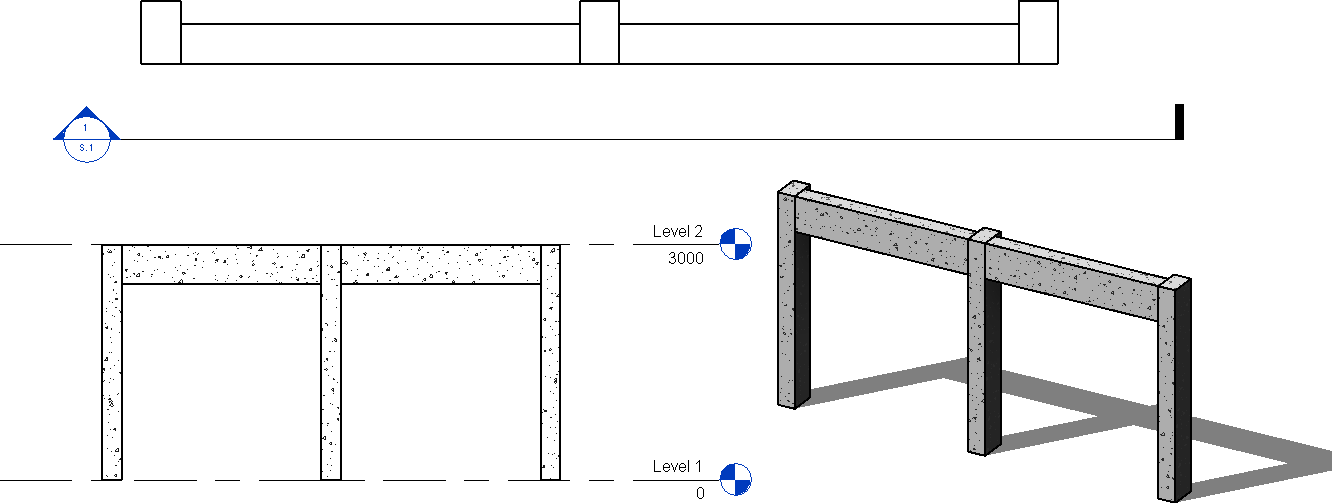
I have a structure, which contains only frame elements ( beam and column).

enter image description here

From what I know, if I apply point load at the columns on both left and right hand side,and if the beam-column joint is rigid, then the column at the center will experience extra moment, because the beam moment will be transmitted to the center column.

In other words, the center column will take moment because of the beam's existence, am I right?

In order to eliminate this extra moment taken by the center column, can I then set the beam-column join connection as pin? How would the structural behavior changes?

$\endgroup$

3 Answers 3

5
$\begingroup$

Yes this is correct - if you want to eliminate the moments in the columns then a pinned connection between the beam and columns will achieve this.

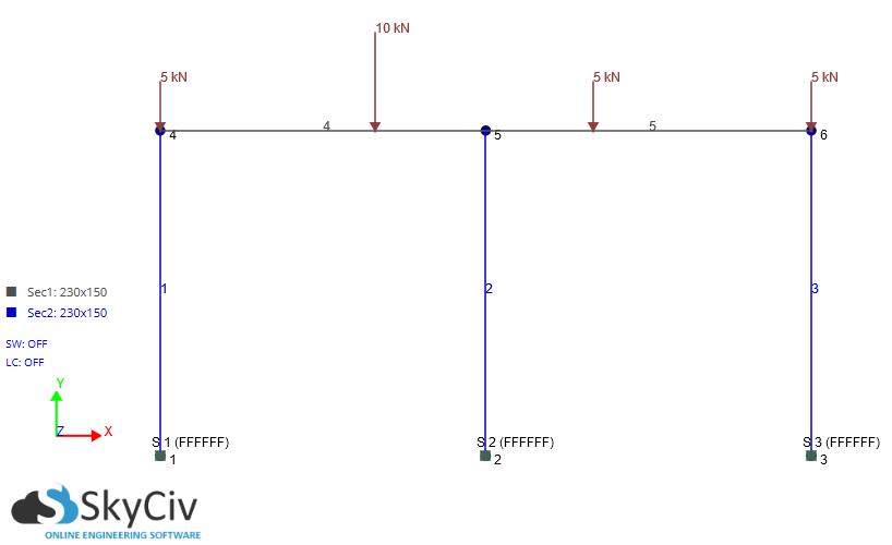
To demonstrate this I have recreated your structure with some imaginary point loads and dimensions in a structural analysis software. The columns are fully fixed at the base.

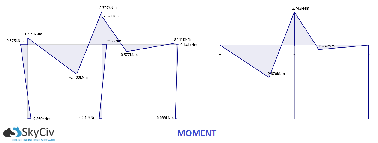
The diagrams on the left the images below have fully-fixed connections, while on the right the columns are pinned connections to the beams.

SkyCiv 3D Structural Analysis Software Input SkyCiv 3D Structural Analysis Software Bending Moment Diagram SkyCiv 3D Structural Analysis Software Axial Force Diagram SkyCiv 3D Structural Analysis Software Deflection Diagram

Most importantly you will notice zero moment in the columns in the right-hand case (pinned connections). Generally this increases axial force and we can see this in the center column. Notice also that the max total displacement (vector sum of X and Y displacement) is larger in the pinned model. When there is a moment acting on the columns, this causes the columns to deflect sideways, whereas in the pinned model there is no sideways deflection (of course no buckling is considered since this is just a linear static analysis).

I hope that helps! I did this really quickly in SkyCiv Structural 3D analysis software if anyone is wondering. If you sign up for a free account a small structure like this can be solved in SkyCiv Structural 3D.

$\endgroup$
6
$\begingroup$

As @pauloz1890 has already stated in his answer, if you add a hinge to a beam-column connection, you will eliminate the bending moment on your column (assuming no horizontal loads are applied).

That being said, your rendering shows a frame composed of concrete beams and columns. The joints between the beams and columns are clearly monolithic. If this is the accurate representation of your structure and it cannot be modified, then your model must remain as it is, without a hinge (and with bending moment on the columns).

Therefore, you can only add this hinge to your model if you can also add the hinge to the actual structure. There are many ways to do this. If your beams are cast-in-place, then you'll most likely need to adopt a Freysinnet or Menasger hinge (there are a few others, but these are the most common). If, on the other hand, your beams are pre-cast, then there are many different types of bearings which can be used (elastomeric or mechanical).
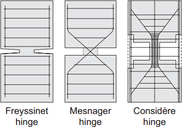
enter image description hereSource (Click "Download full text", free))

And if you choose to modify your structure to allow for hinges, you need to decide how the beams will behave around the central column. Will you have two independent spans (a full hinge), or will you have a continuous beam over both spans (only the column is hinged, this is the example given by @pauloz1890)? This will affect the internal forces on your beams and the axial force distribution between the columns.
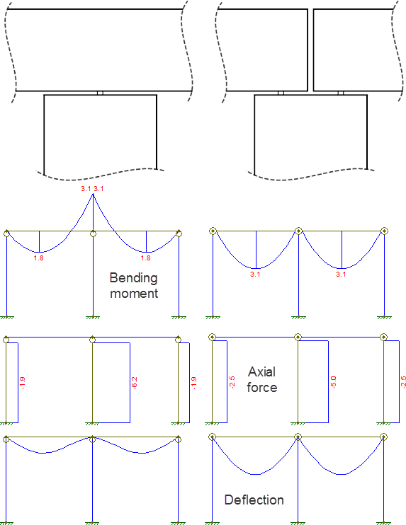
enter image description here

Also note that these models all assume fixed supports at the base of the columns. If a structure is fully hinged at the base and at the joints between all the columns and beams, then it will become hypostatic (unstable). Therefore, in order to define hinged connections between your columns and beams, you must guarantee that the base will be fixed against rotations.

Diagrams obtained with Ftool, a free 2D frame analysis tool.
$\endgroup$
2
  • $\begingroup$ Thanks Wasabi; is the left most and the right most joint also hinged? And what about the bending moment behavior at column for these two cases? $\endgroup$
    – Graviton
    Commented Jul 22, 2016 at 3:19
  • 1
    $\begingroup$ @Graviton: The big circle symbol on or near the joint represents a hinge. In the left-most model, all of the columns are hinged, while the beam remains continuous. In the right-most model, all of the joints between beam and column are fully hinged, leading to two independent spans which behave like simply-supported beams. $\endgroup$
    – Wasabi
    Commented Jul 22, 2016 at 10:14
0
$\begingroup$

If you add hinge to center post you are still going to have loads carried by the center post. The only way to isolate the center post from any load on the lateral posts is to have the 2 side post-beam joints pin connection as well as the center post.

$\endgroup$
2
  • $\begingroup$ Can you elaborate on your answers? Doesn't seem to address my question $\endgroup$
    – Graviton
    Commented Jul 29, 2016 at 22:58
  • $\begingroup$ Let's say you have the beam-column connection at the center post pin but at the side columns fixed connection! If you have unequal loads on the side columns depending on the stiffness of those members you will have unequal shear at their end where they meet the sides of the center post as per your schematic. A force couple acting on the two sides creating creating a moment. Let's call the reaction from left post on the center post RL and the one from right RR the moment will be: M=(RL-RR)/(post width). But if you have all the post-beams pin connected you won't have moment at the center post! $\endgroup$
    – kamran
    Commented Jul 30, 2016 at 1:46

Your Answer

By clicking “Post Your Answer”, you agree to our terms of service and acknowledge you have read our privacy policy.

Not the answer you're looking for? Browse other questions tagged or ask your own question.