1
$\begingroup$

I have some Shape Memory Alloy wire programmed to curl from a straight beam into a circle. The force this generates is approximated as a uniform distributed bending moment along the length of the wire. As the ends of the wire approach to close the circle, I put a pencil in between so that the bending wire "pinches" and grips the pencil. What equations could I use to predict the "pinching (gripping)" force assuming I know the magnitude of the distributed moment? I'm imagining starting from a two-hinged arch and approximating the distributed moment as a concentrated moment at the center of the beam, but am struggling to find example equations that would fit, and I'm really rusty on my free body diagrams.

I did find a similar approach for a three-hinged arch, but I'm not sure those equations apply.

I'm also aware that the bending moment shrinks as the wire approaches its maximum (no load) curled deflection, but I'm OK assuming it's constant at all deflections for now.

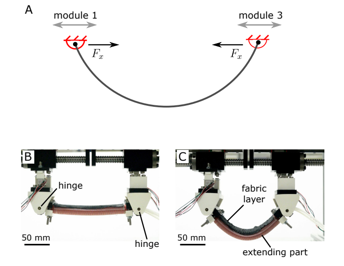
Here's an image of an actuator I found in a paper that is doing the same type of motion by inflating a balloon which causes this beam to bend. They don't provide any equations though; just raw force measurements on some lab equipment.

Example of what I am trying to find

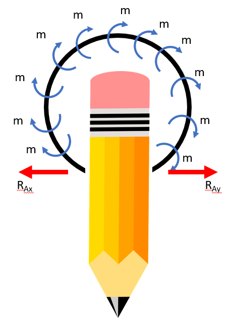
EDIT: Here's my attempt at a FBD, but I know I'm missing things I'm not sure on.:

enter image description here

$\endgroup$

2 Answers 2

1
$\begingroup$

I agree with PM-14's approach to the analysis. Curling of the unrestrained alloy should be into a circular form.

Maximum moment whilst gripping the pencil will be at the top, where the lever arm (perpendicular to the gripping force) is longest ($h_{max}$): $$M_{max} = F_{grip}\cdot h_{max}$$

I do not fully comprehend the curling mechanism, but it is very much possible, that the maximum moment is independent of it. So it would depend just on classic mechanical properties of the "beam": $$\sigma = -z\cdot \frac{M}{I_y}$$

where $z$ is maximum distance from the neutral axis in the beam section and $I_y$ is the second moment of area with respect to $y$ axis.

Combining the 2 equations and setting $z$ to half of the beam section height $b/2$ and stress $\sigma$ to maximum allowable stress $f$: $$F_{grip} = 2\frac{f\cdot I_y}{b\cdot h_{max}}$$

Finally, assuming that the original length of the gripper is $L$ (and it does not change when curling) and it will bend to a circle with diameter $h_{max}$ the formula can be expressed as this

$$F_{grip} = 2\pi\frac{f\cdot I_y}{b\cdot L}$$

Simplifications:

  • Combination of stiff and extending layers will increase overall length when curled.
  • There is most likely some pre-stress after the curling before any external loading is applied.
  • I used formula for stress in straight beam, where the axial stress from bending varies linearly across the section, but this is no longer the case for curved beams, where more complicated formulae would be applied.
$\endgroup$
4
  • $\begingroup$ To clarify the difference between our approaches, your formula gives the pinch force as a function of the extreme fibre stress at the top of the ring (point 'A' in my diagram), measuring stress via strain is however likely to be quite difficult in this situation. My solution (although I haven't actually derived the formulae) would give the force as a function of the material properties and deflection, which is more general and easier to measure. $\endgroup$
    – PM-14
    Commented Jul 25, 2022 at 11:21
  • $\begingroup$ Note you've switched from 'Iy' to 'Jy' half way through your post - 'J' is usually used for torsion constants. Shouldn't be any 'prestress' or lengthening, assuming Euler-Bernoulli beam theory. $\endgroup$
    – PM-14
    Commented Jul 25, 2022 at 11:25
  • $\begingroup$ You are right that 'I' is more common (I will edit that). Prestress will be there, because curling is caused by memory alloy bar trying to extend while being tied to fabric layer at one side, that doesn't want to extend. $\endgroup$ Commented Jul 25, 2022 at 17:07
  • $\begingroup$ True in that case there would be prestress (as per the case of the photos), but I got the impression from the op that the wire is unrestrained, it curls due to its shape memory properties rather than expansion restrained along one edge. $\endgroup$
    – PM-14
    Commented Jul 25, 2022 at 17:47
0
$\begingroup$

In the unrestrained case where there is no pencil and the ring can deform freely, the bending moment is zero. This may seem counterintuitive, but bending moment only arises in the ring when an external deformation is applied. The changing of shape of the wire as it curls is due to internal deformation of the crystalline lattice rearranging to another energy state, and where no external constraints are applied the shape can change freely to accommodate the new arrangement. There will be no global through-section stress gradient ('internal bending moment'), although there may be random locally locked in stress discontinuities in the crystal lattice.

An analogous case to the above would be when a thermal gradient is applied across the section of a straight metal (say steel) rod, which causes it to bend. If allowed to bend freely, there will be no resultant bending moment created, the change in shape is simply due to a physical change in the material structure. If however the rod is constrained to remain straight when it wants to curve under the thermal gradient, a bending moment will be developed due to the 'locked in stress'. In the case of the above wire then, a bending moment will arise only when the rod is constrained from curling as far as it would like, in this case due to the pencil.

To determine this bending moment at any given point around the wire, you can therefore consider the horizontal reactions at the pencil acting at a vertical distance 'h' above the reaction. For a point then at height = h, moment at h Mh = Fb * h. See diagram below: Diagram of moment at height 'h' in wire
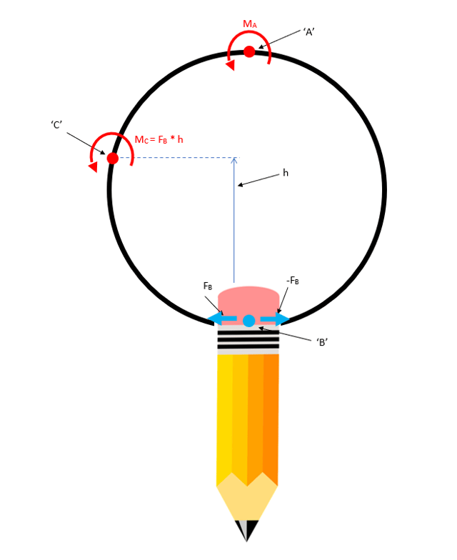
To obtain the actual reaction force based on the imposed deformation would be more complicated. Starting by taking the basic formula relating transverse force and deflection for a cantilever beam as below:
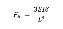
enter image description here

('E' is elastic modulus of wire material, 'I' is second moment of area of perpendicular cross section, 'L' is length from force 'F' to the point of fixity)

You could extend this formula to give the 'x' (horizontal) component of deflection for a finite beam element in any orientation relative to the fixed axes of the system. Then considering the case where the finite element tends to an infinitesimal element: for our case of the wire, the internal moment at a point will be equal to Fb * h as described above, and the x deflection will become a function of 'h' and 'theta'(orientation of element, which is connected to angle of rotation to element from point 'A' to point 'B). 'Theta' can also be rewritten as a function of 'h' so the whole thing can be expressed in terms of 'h'. You can then integrate around the arc from point 'A' to point 'B' (from h=height of ring, to 0) to obtain the relation between deflection and reaction force. (By symmetry both sides of the ring are equal and opposite).
$\endgroup$

Your Answer

By clicking “Post Your Answer”, you agree to our terms of service and acknowledge you have read our privacy policy.

Not the answer you're looking for? Browse other questions tagged or ask your own question.