Given a plant with a transfer function of K/s, how can I tune a PID to control it? I found articles explaining how to tune an integrator with time delay, but not for just a pure integrator system.
-
1$\begingroup$ Integrator-BodeD Integrators assumed to be phase shifted with -90 degrees. One can also achieve the response by combining multiple inputs on Bode Diagram, to see the Magnitude and Phase Shift of system. $\endgroup$– kfbCommented Jun 21, 2017 at 7:56
-
1$\begingroup$ Also, you can check these links: 1-Robotics , 2-Quora and 3-Quora, If the problem is satisfied, I can edit these solutions into answer to prevent link rot. (Also, you might need to edit the title, because PID stands for Proportional-Integral-Derivative, and in this case we need the tune only Integral controller.) $\endgroup$– kfbCommented Jun 21, 2017 at 8:41
-
$\begingroup$ Can you provide more information about what you're trying to accomplish, and what part is causing you trouble? Are you trying to design a PID controller, or are you trying to experimentally tune one? Is the plant model perfectly known (i.e. you know $K$)? $\endgroup$– BarbalatsDilemmaCommented Jun 21, 2017 at 14:51
-
$\begingroup$ Thanks for your answers, this migh be a dumb question but here it is. I'm trying to keep the water level in a tank at a given value by controlling the flow in, the input is the flow and the output is the level. i think that the level is related to the flow by : dL/dt = Q/A where Q is the flow and A the area of the tank. The transfer function is then TF=1/(A*s) How can i design a PID controller for the closed loop system? PS : excuse my bad english $\endgroup$– Pr. GiratinaCommented Jun 22, 2017 at 7:20
-
$\begingroup$ This problem is actually a quite common one. If the details are provided I can happily help you. $\endgroup$– kfbCommented Jun 22, 2017 at 12:46
1 Answer
Ideal Water Tank
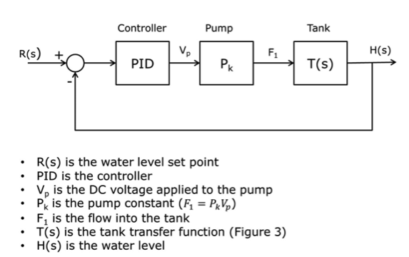
The closed-loop water level control system looks like Figure.

Figure. Closed-loop water level control system
Figure 3 can be used as mentioned in comment above :
T(s) = 1 / ( A * s ) where Flow = Area * ( dHeight / dTime )
If all parameters set (positively), this system will be stable also. Changing controller parameters will change the response of system but not the stability.
- MATLAB Simulink can be also used in the design process.
Selecting Controller Parameters
One can choose different controller parameters for K1, K2*s, K3/s terms. This will only change the general response behaviour of system but this will not change the stability of system, so it will remain stable.
There are multiple ways to select them;
- Inspect the Previous Applications
- Inspect the Articles about the subject if unique
- Design
In the design process, one must consider the requirements of the system. Also in some preferred programs like MATLAB can be useful with Simulink in the design process. There are number of common terms in transient response characteristics and which are;
- Delay time (td) is the time required to reach at 50% of its final value by a time response signal during its first cycle of oscillation.
- Rise time (tr) is the time required to reach at final value by a under damped time response signal during its first cycle of oscillation. If the signal is over damped, then rise time is counted as the time required by the response to rise from 10% to 90% of its final value.
- Peak time (tp) is simply the time required by response to reach its first peak i.e. the peak of first cycle of oscillation, or first overshoot.
- Maximum overshoot (Mp) is straight way difference between the magnitude of the highest peak of time response and magnitude of its steady state. Maximum overshoot is expressed in term of percentage of steady-state value of the response. As the first peak of response is normally maximum in magnitude, maximum overshoot is simply normalized difference between first peak and steady-state value of a response.
The controller parameters so the characteristics of the system must satisfy the system requirements. There are more formulas about each of them depending on the systems characteristic equation's order etc. While changing parameters, it will be useful to simulate the response to visualize the problem.
Desing section can be extended more. Tutorials for: System Analysis and PID-Design. There are detailed lectures in the site too. I can update the answer if there is some missing points.