6
$\begingroup$

Following on from this answer, I am reading about the difference between hinge and pin connections here, and I don't quite understand about it. I think I would need to see the mathematical representation ( the boundary condition) involving pin and hinge connection, in order to actually understand it.

How can I represent, in mathematical terms, the pin and hinge connection? And how can it be represented in the Stiffness matrix method, as boundary conditions (maybe)?

$\endgroup$
0

3 Answers 3

7
$\begingroup$

I believe you have chosen a poor reference. Indeed, that link has absolutely nothing to do with structural analysis, but rather a specific implementation in steel structures.

A pinned support is a boundary condition which restricts all displacements but allows the structure to rotate.

A hinge (more formally, an internal hinge), on the other hand, is a description of the structure's behavior. Specifically, it removes the rotation compatibility between bars around a node (between all bars or a subset of them), thereby increasing the structure's degrees of freedom.

For a more visual demonstration of the difference, here's a structure with four pinned supports, along with its deformed configuration under the effect of a uniform load. You'll notice that the supports allow the structure to rotate around them, however one beam's inclination at a given node must be equal to the inclination of the neighboring beam on the same node, meaning there may be no discontinuity in the derivative of the deflection at the support (compatibility of rotations).

enter image description here

And now two variations on the same structure with the same loading, but with an internal hinge at different locations.

enter image description here

In this case, an internal hinge is placed on the same position as one of the supports. This removes the compatibility of rotations around that node, leading to a clear discontinuity in the derivative of the deflection around that support.

enter image description here

Now the hinge is placed in the middle of the central span, leading to a clear discontinuity in the derivative of the deflection at that point.

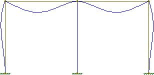
Hinges can also be placed to just one side of a node. For instance, look at the deflection of this frame under a uniform vertical load and a concentrated horizontal load.
enter image description here

The columns and beams all maintain their original perpendicularity. Specifically at the central column, notice that the beams maintain their angular compatibility (no discontinuity in the derivative of the deflection).

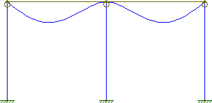
If, however, we add hinges to the tops of the columns:
enter image description here

The beams and columns no longer remain perpendicular in their deflected state. The beams over the central column, however, maintain their angular compatibility.

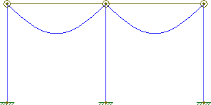
If, however, the nodes were fully hinged, then each span would behave independently like a simply-supported beam:
enter image description here


In the direct stiffness method, the fundamental equation is

$$\{q\}=K\{d\}$$

A pinned support defines the contents of $\{d\}$, by setting the degrees of freedom of the given node to $(d_x, d_y, \theta) = (0, 0, \theta)$ (in the case of a 2D structure). An internal hinge, on the other hand, increases the dimensions of the calculation, since it increases the number of degrees of freedom. So, instead of a node having merely $(d_x, d_y, \theta)$, it will have $(d_x, d_y, \theta_1, \theta_2, \theta_3, ...)$, where $\theta_i$ represents the rotation on different sides of the hinge.

$\endgroup$
4
  • $\begingroup$ An answer on the basis of an internal hinge is not appropriate for the question asked. It would be appropriate if the OP had mentioned anything which relates to internal hinges, and then said the link had confused him with respect to that. From the current question I infer that the OP started from the link, and has questions about the terms as used in the link. $\endgroup$
    – AndyT
    Commented Jul 25, 2016 at 8:29
  • $\begingroup$ @AndyT, the OP actually started by asking this question. I answered that question and the OP and I had a little chat beneath my answer where they explicitly mentioned this question was related to that one. Perhaps the OP should have added a reference to that original question in this one. $\endgroup$
    – Wasabi
    Commented Jul 25, 2016 at 10:05
  • 1
    $\begingroup$ Fair enough. That definitely makes this the answer the OP needs, I will therefore edit the reference into the question to make it clearer. (I would also happily turn my downvote into an upvote, but it's locked until your answer is edited.) $\endgroup$
    – AndyT
    Commented Jul 25, 2016 at 10:34
  • $\begingroup$ I've made a whitespace edit to your answer to unlock the votes and re-cast my vote. $\endgroup$
    – AndyT
    Commented Jul 25, 2016 at 10:37
4
$\begingroup$

I'm not sure if the use of the term 'hinge' in this context is common in engineering design (at least I haven't heard of it being used in this way).

In the website you link to they seem to be referring to the difference between steel connections that freely allow rotations ('pins') and those where connection rotation is restrained in practice ('hinges') - they claim in this case because more than one bolt is used. I feel that this is a poor explanation of what is happening.

The most common connection type for steel structures are Simple Connections. These connections are assumed to not transfer any bending. Engineers typically call such connections 'pins' regardless if they are built with a physical pin or not. Mathematically these are modelled as:

$$\frac{d^2 w}{dx^2} = M = 0$$

where w is the displacement as a function of the distance along the beam (x), and M is the bending moment. Because of the way these connections are constructed a small rotation at the connection will be allowed due to: tolerance in the bolt holes, shear deformation of the bolts, etc. Since small deflections are assumed (a common assumption in engineering) this means there will only be a small error by assuming that the connection is free to rotate.

However, if there is a requirement to accommodate large rotations. For example, in cable structures, or perhaps where large thermal deformations are expected. The connection can be constructed with a physical pin to accommodate this. However, mathematically the boundary condition is the same (M = 0). Note that pins are also used in practice for ease of assembly and aesthetic purposes.

If you wanted to know the difference in terms of mathematical boundary conditions between a simple bolted connection and a true pin you could perhaps state it as:

True Pin: $$\frac{d^2 w}{dx^2} = M = 0$$

Simple bolted connection: $$\frac{d^2 w}{dx^2} = M \approx 0$$

There is a reasonable amount of engineering judgement which goes into deciding if a connection can be designed assuming zero bending moment at the connections.

The alternative to these connections is 'fixed' or 'moment resisting' connections. These are designed (and constructed) such that bending is transferred through the connections ($ M \neq 0$).

$\endgroup$
1
  • $\begingroup$ +1. And seconded that the article's use of "hinge" is unusual. $\endgroup$
    – AndyT
    Commented Jul 22, 2016 at 14:46
0
$\begingroup$

If you compare their construction, it is very similar. They both resist shear and axial loading but have no bending momentum. I guess the real difference is in the type of constructions where they're used and in the way they're bolted. My thinking is that pin connections are used for "heavy-duty" steel construcions, while hinges are used for light structures. Also hinges are connected with multiple bolts...

Hope this helps.

$\endgroup$
1
  • $\begingroup$ Would you like to provide some mathematical formulation how these two differ? $\endgroup$
    – Graviton
    Commented Jul 22, 2016 at 8:03

Your Answer

By clicking “Post Your Answer”, you agree to our terms of service and acknowledge you have read our privacy policy.

Not the answer you're looking for? Browse other questions tagged or ask your own question.