5
$\begingroup$

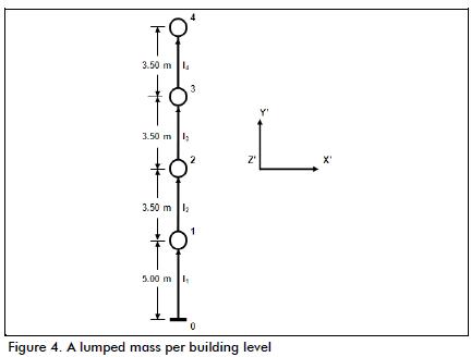
Intuitively, building can be represented as a lumped mass model ( the taller the merrier!):

enter image description here

Assuming a building is a lumped mass cantilever column also makes the global stability checks easier because building codes often assume building structure as a cantilever column.

But if my building structure is discretized and response analyzed in terms of FEM ( with column/beam as line element, and slab/wall as area element), then is it possible that, from the stiffness matrix and everything I have in FEM, I can still approximate the structure as a lumped mass model? If yes, how to do it? How to calculate the errors involved?

A practical application of doing this is in this question. But for the purpose of this question, let's assume that I do it for academic purpose and don't really want to care about the application.
$\endgroup$
12
  • $\begingroup$ An idea would be to consider each element of the FEM grid as a lumped mass. $\endgroup$
    – Karlo
    Commented Mar 1, 2016 at 8:21
  • 1
    $\begingroup$ @MWijnand, would you like to be more explicit about that and post it as an answer? $\endgroup$
    – Graviton
    Commented Mar 1, 2016 at 8:50
  • $\begingroup$ I am not an expert in FEM, though. I think that I cannot (yet) contribute enough of information for a full answer. $\endgroup$
    – Karlo
    Commented Mar 1, 2016 at 8:52
  • $\begingroup$ Your question here is fairly broad. It might help if you elaborated on what your objective is? What are you trying g to use this lumped mass model for? If you're after the OTM, my answer on your other question explains how you can do that with your existing FE model. $\endgroup$ Commented Mar 1, 2016 at 15:32
  • $\begingroup$ So you want to take the results of an FEA and build a mass and stiffness matrix from it? $\endgroup$ Commented Mar 1, 2016 at 18:19

1 Answer 1

-1
$\begingroup$

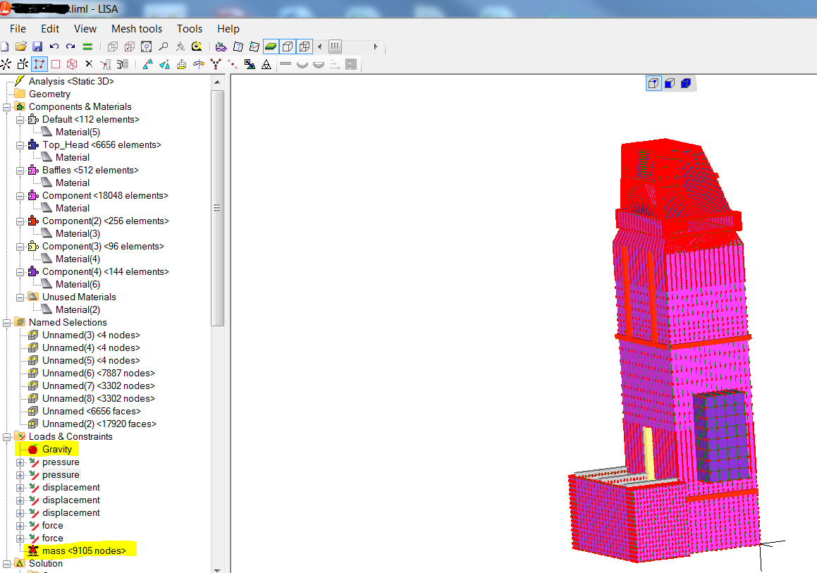
I perform this kind of analysis all the time when running pressure vessels and other scrubbers, using LISA:enter image description here

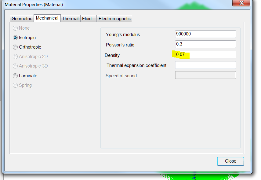
As you can see, I have the option to add lump mass onto individual nodes (for my "live loads", or other non structural dead weight), and my material has a density option available:

enter image description here

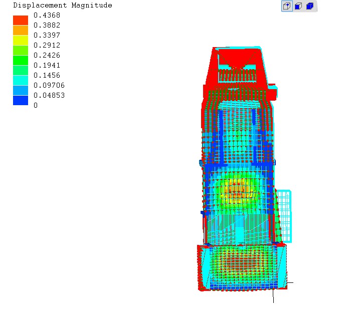
Typically, I set a 1g gravity load downwards, and then plan my seismic loading based upon code. ASCE for scrubbers and vessels has a few variations, depending on the designers discretion. I use the most conservative one with this method however, and go with a horizontal gravity in one of the main directions, equal to SDS * I / R. Since LISA is not a non-linear FEA, this does not get P-Delta effects, but still gets displacements and stresses:

enter image description here

As you can see, the scrubber has shifted slightly to the left under the seismic loading (the internal vacuum is doing most of the displacement though). The software has automatically lumped the mass of the individual structural elements (as given in the "density" dialog for material) to the middle of the individual elements. I place the live load mass directly on top of the applicable elements. This way, the gravity load will affect them completely. Then, it spits out the displacements and stresses.

Since I don't have P-delta effects from my linear FEA, I will typically go back to the drawing board, and make a lumped mass model for buckling analysis. While the FEA is done in fine strokes and small elements, this is done by hand instead.

$\endgroup$
1
  • $\begingroup$ I am not talking about using a software package to do it; I am talking about writing a software package to model this $\endgroup$
    – Graviton
    Commented Jun 25, 2016 at 2:36

Your Answer

By clicking “Post Your Answer”, you agree to our terms of service and acknowledge you have read our privacy policy.

Not the answer you're looking for? Browse other questions tagged or ask your own question.