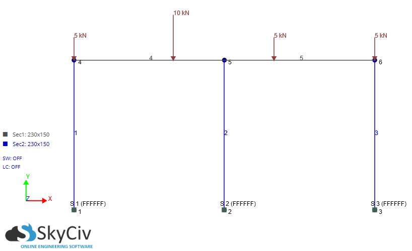
Let me start by answering your second question: models such as this one, which involve only one-dimensional beam elements, are 100% analytical and can therefore always in theory be understood intuitively. There is no "FEM behavior" for such models. Sometimes the models may get complex with lots of bars and whatnot, which may make "intuitive explanations" more difficult, but the result will always be analytical.
Let's start by looking at statement B:
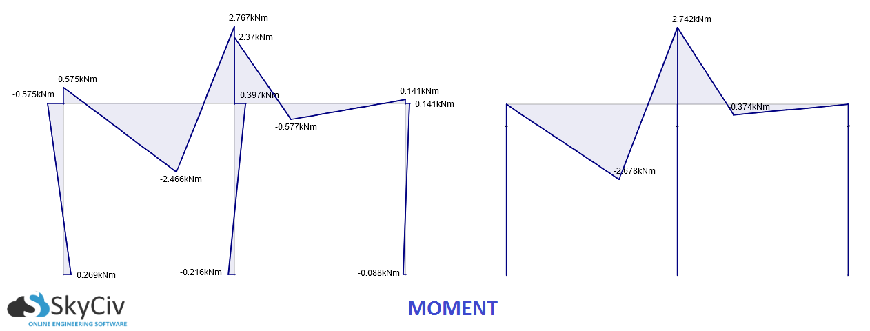
Now, let's take a look at beam 4 in your model (the left-most beam). More specifically, it's bending moment diagram. As you've noticed, the pinned model displays zero moment at the left-most column. This is the very definition of a hinge and is expected behavior. The moment on the beam at the central column is non-zero because the beam itself is not hinged, but the central column is hinged and therefore displays zero moment at the node.
Now, on to statement A, starting by looking at the beam's deflection:
Let's keep looking at the bending moment diagram. The beam equation tells us that
$$\dfrac{\partial^2 }{\partial x^2}\left(EI\frac{\partial^2 w}{\partial x^2}\right) = q$$
which also tells us that
$$EI\frac{\partial^2 w}{\partial x^2} = M$$
that is: bending moment (divided by stiffness $EI$) is the second derivative of deflection. From calculus, we know that the second derivative of any function described the function's curvature. So bending moment describes deflection's curvature, which describes the "acceleration" with which the beam's tangent (the first derivative of deflection, and therefore bending moment's integral) changes.
So, the more balanced a bending moment diagram is between positive and negative bending moment, the more the total "acceleration" cancels itself out, implying in smaller tangent changes, and therefore smaller deflections. So yes, a fixed node will always lead to smaller deflections
To answer the matter of the node's displacement, we first need to explain point statement C. For that we need to look at beam 4 in isolation. To do so, we need to replace the surrounding beams with elastic supports which describe their stiffness.
- The vertical supports' stiffness will be equal to the columns' axial stiffness (the node with the central column will also have a tiny addition due to the other beam's stiffness against imposed transversal displacements)
- The horizontal supports' stiffness will be equal to the columns' stiffness against imposed transversal displacements
- The rotational supports' stiffness will depend on the boundary conditions. If hinged, then the outer node will have zero stiffness and the central node will have a stiffness equal to the other beam's stiffness against imposed rotations. If fixed, then both nodes will have the columns' stiffness against imposed rotations, adding the other beam's stiffness as well for the central node.
So, basically, the only difference between the hinged and fixed cases is in the rotational stiffness (as would intuitively be expected). This increased stiffness, however, causes the node to pull in a greater proportion of all forces, thereby increasing the axial forces in your outer column and reducing them in the central column in the fixed model.
Returning to the issue of the node's deflections, they are now easy to explain. After all, in the fixed model the column suffers more axial forces, naturally increasing the vertical deflections. But it also suffers bending moment, which generates horizontal deflections as well as a tiny bit of additional vertical deflection.


