0
$\begingroup$

I have heavily edited the question, as its previous standing was quite hopeless

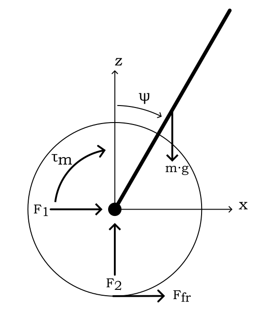
Thinking about a simple model of a unicycle, where the rider is a uniformly distributed rod and the unicycle just consists of a wheel that is being powered by a motor; as shown in the below free body diagram:

enter image description here

Considering that the motor and the body (in this case this is just the rider modeled as the uniform rod) are rigidly connected, then the dynamics can be analysed to try and come to some useful conclusions.

I am trying to understand how the power of the motor can control the orientation of the rod, and so as a thought experiment I wanted to find the torque input that would cause the rod to stay statically upright for a given angle of $\psi$.
Because the motor and the body are rigidly connected the torque exerted by the motor onto the wheel is felt by the body in equal and opposite magnitude (N3L); and I am assuming both these torques to originate at the centre of the disk that is modeling the wheel and I am calling the torque exerted onto the wheel by the motor to be $\tau_m$.

Taking moments about the centre of the disk, the moments felt by the body should be $-\tau_m$ and $m \cdot g\cdot l\cdot sin\psi$, which would imply for the moments to cancel $$\tau_m=m \cdot g\cdot l\cdot sin\psi$$ $l$ is the distance from the centre of the disk to the centre of mass of the rod.
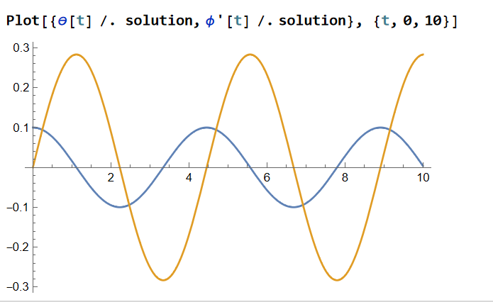
This seems plausible and would cause the acceleration of the wheel, however when I simulate it (where dynamics are derived using Euler Lagrange Equations and a numerical solver is used) I get counter intuitive results. As shown:

enter image description here

The blue line is the value of $\psi$ and the orange line is the value of $\phi$, which hasn't been included on the free body diagram but is the angle of the wheel.
In case someone would like to replicate the results, all parameters apart from g were set to 1 and g set to 10: $$ L = \frac{1}{2} [m_w R^2 \phi ^2 + I_w \phi ^2 + m_b (l^2 \dot{\psi}^2 \sin ^2 \psi + [l \dot{\psi} \cos \psi + R \dot{\phi}]^2) + I_b \dot{\psi}^2] - g m_b l \cos \psi] \\ Q = \tau_m \frac{\partial}{\partial q} (\dot{\psi} - \dot{\phi}) \\ \tau_m \rightarrow m \cdot g\cdot l\cdot sin\psi $$

So Why doesn't $\psi$ stay static when simulated; furthermore Would the torque created by the weight of the rider on the body have an equal and opposite reaction torque at the wheel? If this second statement is true then for a friction less system the value of torque stated should bring the system to a static equilibrium.
$\endgroup$
4
  • $\begingroup$ It would be useful to have a diagram with symbols indicated on it ($x,\ \theta,\ \zeta$, center of mass of the system, axle, point of contact of wheel with the ground etc.)to go along with the paragraph on physical explanation. You seem to calculate moment about the axle of the wheel. I think the point of contact of the wheel with the ground is a better reference since it is the instantaneous center of rotation (I'm not sure though). It would also be helpful to see the derived equations (if they are not too complicated). Consider editing the question. $\endgroup$
    – AJN
    Commented Nov 30, 2022 at 16:49
  • 1
    $\begingroup$ A free body diagram would also help in refining your intuitive understanding. $\endgroup$
    – AJN
    Commented Nov 30, 2022 at 16:50
  • $\begingroup$ @AJN will be working on it. Would probably resort to MS paint, unless theres an application you could recommend for model drawing? $\endgroup$ Commented Nov 30, 2022 at 18:09
  • $\begingroup$ forward lean is detected by a tilt sensor $\endgroup$
    – jsotola
    Commented Nov 30, 2022 at 21:19

3 Answers 3

1
$\begingroup$

Think of it like this. When the user leans forward their weight will no longer be directly over the point where the wheel touches the ground, this offset force creates a torque which can be easily calculated using statics.

The balancing vehicle must at least match this torque, or it will fall forward. It does this by pushing laterally against the ground, which has the "side effect" of moving the vehicle forward.

So if we assume the user adjusts their body position to create a constant lean forward, it will correspond to a constant motor output torque until some limit is reached.

The balancing vehicle can also deliver a torque greater or less than the equilibrium torque. This has the effect of pushing the user back, or forward. This can be used with a cascaded feedback loop to control a vehicle without a rider.

So effectively, yes you can control the velocity, it's a bit complicated though: You control the velocity by varying the torque, And you vary the torque target by varying the payload tilt angle. And you vary the payload tilt angle by adjusting the output torque to greater or less than the equilibrium value. It's a lot of feedback loops.

$\endgroup$
0
$\begingroup$

It is more complicated than this. You need gyroscopes, otherwise you will need constant acceleration and eventually the motor will run out of power (or the user will end up at 120+ kph and die). The angle is maintained by gyros; acceleration is only one part of the equation and must be limited.

$\endgroup$
1
  • $\begingroup$ The original post does not rule out the presence of gyros (angle measurement). $\endgroup$
    – AJN
    Commented Dec 1, 2022 at 12:47
0
$\begingroup$

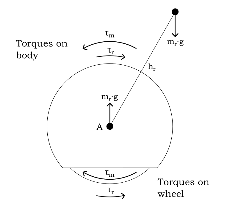
I am considering the system to be 2 rigid bodies - the wheel and the body (which is the chassis + rider); where the wheel and the body are connected at the axle.
enter image description here

Assuming that the frictional torque at the wheel and the body are some function of the difference between their relative angular velocities and moments are measured clockwise: $$\tau^{Fr}_{w} = -\mu_w(\dot{\phi} - \dot{\theta}),\; \tau^{Fr}_{b} = -\mu_b(\dot{\theta} - \dot{\phi})$$ The statics lead to the following calculations for a given tilt angle of the rider ($\theta$) and given torque delivered by the motor ($\tau_m$).

Forces and reaction forces from N3L
Torque at wheel due to torque of the motor: $\tau_m$
$\implies$ Reaction at body: $-\tau_m$
Torque at body from rider position: $m_r g sin(\theta) h_r$
$\implies$ Reaction at wheel: $-m_r g sin(\theta) h_r$

Moments about wheel $$M(w) = \tau_m -m_r g sin(\theta) h_r + \tau^{Fr}_w \equiv \tau_m -m_r g sin(\theta) h_r -\mu_w(\dot{\phi} - \dot{\theta})$$

Moments about body $$M(b) = m_r g sin(\theta) h_r - \tau_m + \tau^{Fr}_b \equiv m_r g sin(\theta) h_r - \tau_m -\mu_b(\dot{\theta} - \dot{\phi})$$

Assuming that body of EUC is to stay stationary $$\dot{\theta} = 0 \\ M(b) = 0 \implies \tau_m = m_r g sin(\theta) h_r -\mu_b(\dot{\theta} - \dot{\phi})$$

Substituting result into moments of wheel $$M(w) = m_r g sin(\theta) h_r -\mu_b(\dot{\theta} - \dot{\phi}) -m_r g sin(\theta) h_r -\mu_w(\dot{\phi} - \dot{\theta}) \equiv -\mu_b(\dot{\theta} - \dot{\phi}) - \mu_w(\dot{\phi} - \dot{\theta}) \\ -\mu_b(\dot{\theta} - \dot{\phi}) = \mu_b(\dot{\phi} - \dot{\theta}) \implies M(w) = (\mu_b - \mu_w)(\dot{\phi} - \dot{\theta})$$

All this is to say that any acceleration in the wheel by the controller is caused by the difference in friction between the body and the wheel, and if they were the same no motion would occur (instead the tilted rider of the body and the wheel would be in static equilibrium).

$\endgroup$

Your Answer

By clicking “Post Your Answer”, you agree to our terms of service and acknowledge you have read our privacy policy.

Not the answer you're looking for? Browse other questions tagged or ask your own question.