made math expression work
Source Link

I have heavily edited the question, as its previous standing was quite hopeless

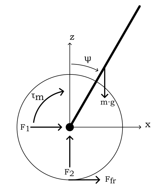
Thinking about a simple model of a unicycle, where the rider is a uniformly distributed rod and the unicycle just consists of a wheel that is being powered by a motor; as shown in the below free body diagram:

enter image description here

Considering that the motor and the body (in this case this is just the rider modeled as the uniform rod) are rigidly connected, then the dynamics can be analysed to try and come to some useful conclusions.

I am trying to understand how the power of the motor can control the orientation of the rod, and so as a thought experiment I wanted to find the torque input that would cause the rod to stay statically upright for a given angle of $\psi$.
Because the motor and the body are rigidly connected the torque exerted by the motor onto the wheel is felt by the body in equal and opposite magnitude (N3L); and I am assuming both these torques to originate at the centre of the disk that is modeling the wheel and I am calling the torque exerted onto the wheel by the motor to be $\tau_m$.

Taking moments about the centre of the disk, the moments felt by the body should be $-\tau_m$ and $m \cdot g\cdot l\cdot sin\psi$, which would imply for the moments to cancel $$\tau_m=m \cdot g\cdot l\cdot sin\psi$$ $l$ is the distance from the centre of the disk to the centre of mass of the rod.
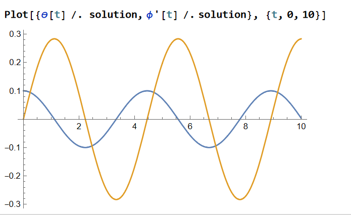
This seems plausible and would cause the acceleration of the wheel, however when I simulate it (where dynamics are derived using Euler Lagrange Equations and a numerical solver is used) I get counter intuitive results. As shown:

enter image description here

The blue line is the value of $\psi$ and the orange line is the value of $\phi$, which hasn't been included on the free body diagram but is the angle of the wheel.
In case someone would like to replicate the results, all parameters apart from g were set to 1 and g set to 10:

$$ L = \frac{1}{2} [m_w R^2 \phi ^2 + I_w \phi ^2 + m_b (l^2 \dot{\psi}^2 \sin ^2 \psi + [l \dot{\psi} \cos \psi + R \dot{\phi}]^2) + I_b \dot{\psi}^2] - g m_b l \cos \psi $$ $Q = \tau_m \frac{\partial(\dot{\psi} - \dot{\phi})}{ \partial{\dot{q} } \equiv \tau_m \cdot (1,-1)^T$ $$\tau_m \rightarrow m \cdot g\cdot l\cdot sin\psi $$$$ L = \frac{1}{2} [m_w R^2 \phi ^2 + I_w \phi ^2 + m_b (l^2 \dot{\psi}^2 \sin ^2 \psi + [l \dot{\psi} \cos \psi + R \dot{\phi}]^2) + I_b \dot{\psi}^2] - g m_b l \cos \psi] \\ Q = \tau_m \frac{\partial}{\partial q} (\dot{\psi} - \dot{\phi}) \\ \tau_m \rightarrow m \cdot g\cdot l\cdot sin\psi $$

So Why doesn't $\psi$ stay static when simulated; forthermorefurthermore Would the torque created by the weight of the rider on the body have an equal and opposite reaction torque at the wheel? If this second statement is true then for a friction less system the value of torque stated should bring the system to a static equilibrium.

I have heavily edited the question, as its previous standing was quite hopeless

Thinking about a simple model of a unicycle, where the rider is a uniformly distributed rod and the unicycle just consists of a wheel that is being powered by a motor; as shown in the below free body diagram:

enter image description here

Considering that the motor and the body (in this case this is just the rider modeled as the uniform rod) are rigidly connected, then the dynamics can be analysed to try and come to some useful conclusions.

I am trying to understand how the power of the motor can control the orientation of the rod, and so as a thought experiment I wanted to find the torque input that would cause the rod to stay statically upright for a given angle of $\psi$.
Because the motor and the body are rigidly connected the torque exerted by the motor onto the wheel is felt by the body in equal and opposite magnitude (N3L); and I am assuming both these torques to originate at the centre of the disk that is modeling the wheel and I am calling the torque exerted onto the wheel by the motor to be $\tau_m$.

Taking moments about the centre of the disk, the moments felt by the body should be $-\tau_m$ and $m \cdot g\cdot l\cdot sin\psi$, which would imply for the moments to cancel $$\tau_m=m \cdot g\cdot l\cdot sin\psi$$ $l$ is the distance from the centre of the disk to the centre of mass of the rod.
This seems plausible and would cause the acceleration of the wheel, however when I simulate it (where dynamics are derived using Euler Lagrange Equations and a numerical solver is used) I get counter intuitive results. As shown:

enter image description here

The blue line is the value of $\psi$ and the orange line is the value of $\phi$, which hasn't been included on the free body diagram but is the angle of the wheel.
In case someone would like to replicate the results, all parameters apart from g were set to 1 and g set to 10:

$$ L = \frac{1}{2} [m_w R^2 \phi ^2 + I_w \phi ^2 + m_b (l^2 \dot{\psi}^2 \sin ^2 \psi + [l \dot{\psi} \cos \psi + R \dot{\phi}]^2) + I_b \dot{\psi}^2] - g m_b l \cos \psi $$ $Q = \tau_m \frac{\partial(\dot{\psi} - \dot{\phi})}{ \partial{\dot{q} } \equiv \tau_m \cdot (1,-1)^T$ $$\tau_m \rightarrow m \cdot g\cdot l\cdot sin\psi $$

So Why doesn't $\psi$ stay static when simulated; forthermore Would the torque created by the weight of the rider on the body have an equal and opposite reaction torque at the wheel? If this second statement is true then for a friction less system the value of torque stated should bring the system to a static equilibrium.

I have heavily edited the question, as its previous standing was quite hopeless

Thinking about a simple model of a unicycle, where the rider is a uniformly distributed rod and the unicycle just consists of a wheel that is being powered by a motor; as shown in the below free body diagram:

enter image description here

Considering that the motor and the body (in this case this is just the rider modeled as the uniform rod) are rigidly connected, then the dynamics can be analysed to try and come to some useful conclusions.

I am trying to understand how the power of the motor can control the orientation of the rod, and so as a thought experiment I wanted to find the torque input that would cause the rod to stay statically upright for a given angle of $\psi$.
Because the motor and the body are rigidly connected the torque exerted by the motor onto the wheel is felt by the body in equal and opposite magnitude (N3L); and I am assuming both these torques to originate at the centre of the disk that is modeling the wheel and I am calling the torque exerted onto the wheel by the motor to be $\tau_m$.

Taking moments about the centre of the disk, the moments felt by the body should be $-\tau_m$ and $m \cdot g\cdot l\cdot sin\psi$, which would imply for the moments to cancel $$\tau_m=m \cdot g\cdot l\cdot sin\psi$$ $l$ is the distance from the centre of the disk to the centre of mass of the rod.
This seems plausible and would cause the acceleration of the wheel, however when I simulate it (where dynamics are derived using Euler Lagrange Equations and a numerical solver is used) I get counter intuitive results. As shown:

enter image description here

The blue line is the value of $\psi$ and the orange line is the value of $\phi$, which hasn't been included on the free body diagram but is the angle of the wheel.
In case someone would like to replicate the results, all parameters apart from g were set to 1 and g set to 10: $$ L = \frac{1}{2} [m_w R^2 \phi ^2 + I_w \phi ^2 + m_b (l^2 \dot{\psi}^2 \sin ^2 \psi + [l \dot{\psi} \cos \psi + R \dot{\phi}]^2) + I_b \dot{\psi}^2] - g m_b l \cos \psi] \\ Q = \tau_m \frac{\partial}{\partial q} (\dot{\psi} - \dot{\phi}) \\ \tau_m \rightarrow m \cdot g\cdot l\cdot sin\psi $$

So Why doesn't $\psi$ stay static when simulated; furthermore Would the torque created by the weight of the rider on the body have an equal and opposite reaction torque at the wheel? If this second statement is true then for a friction less system the value of torque stated should bring the system to a static equilibrium.

major changes to insight on question
Source Link

If this question belongs to physics stack exchange, please let me know and I will transfer it as soon as I can. Please also let me know if a diagram is neccessary of the model (I have not made digital model diagrams before, but can try my best - a recommended product would also be greatly appreciated to this end). Thank you all for any help, this community is appreciated.I have heavily edited the question, as its previous standing was quite hopeless

From now on I will be referring to the longitudinal tiltingThinking about a simple model of the unicycle as 'pitching' as per the yaw-roll-pitch convention.
EUC : Electric Unicycle
Body : Refers to the encasing around a one wheel segwayunicycle, ifwhere the context involves a rider aswell, than the body is the encasinga uniformly distributed rod and the rider (where the rider can pivot about the pedals).
Angle of pitch [$\theta$] : specifically refers to the pitch of the unicycle frame and notjust consists of a wheel that is being powered by a motor; as shown in the rider, which may be different.below free body diagram:

FORWORD:
I have been tasked with creating a optimal feedback controller for an EUC which stabilisesenter image description here
Considering that the vehicle (i.e. stays upright)motor and also moves the EUC with user inputbody (i.e. tilting your body forwards will cause the EUC to accelerate forwards).
The physical model I have derived is based on a one wheeled segway likein this product - External link; the model has been derived using Lagrangian mechanics and I have assumed the only control input to the system to be the torque delivered bycase this is just the motor.
Some key variables ofrider modeled as the modeluniform rod) are given above. It should be noted that the model is currently 2Drigidly connected, butthen the end goal isdynamics can be analysed to have a working modeltry and controller in 3Dcome to some useful conclusions.

STORY: My question is really of a physical nature, but I have posted in engineering to show solidarity with my fellow proffession mates. I have talked to my supervisor for this project and he has told me that there is no needam trying to set a terminal condition, forunderstand how the velocitypower of wheel, on the controller. Since by having an objective tomotor can control the angle of pitchorientation of the uncicyle bodyrod, and have it as close to 0 over the trajectory (condition for stability of the EUC - can be viewedso as controlling the unstable equilibria of an inverted pendulum to make it stable) the controller will naturally accelerate the wheela thought experiment I wanted to offsetfind the pitch angle creating bytorque input that would cause the pitching rider, bringing $\theta$ back to 0. This makes intuitive sense to me but I am lookingrod to formalise it instay statically upright for a simple understandinggiven angle of physics$\psi$.

The physical explanation I have come to is:
Acceleration of wheel in x (assume leaning in direction of +ve x) creates a moment aboutBecause the axle (generated bymotor and the body are rigidly connected the torque ofexerted by the engine) that must be counteractedmotor onto the wheel is felt by a moment in the body of the EUC ofin equal and opposite proportionsmagnitude (N3L) which is required for the two moments; and I am assuming both these torques to cancel outoriginate at the axle and have no angular movement betweencentre of the body anddisk that is modeling the wheel ofand I am calling the EUC.
i.e. Iftorque exerted onto the motor supplies a clockwise moment of $\zeta$,wheel by the body will react with a counterclockwise moment ofmotor to be $\zeta$$\tau_m$. If

Taking moments about the reactionary momentcentre of the body stemming fromdisk, the torque deliveredmoments felt by the motor is equal and opposite of the moment created from the rider pitching his body forwardsshould be (as$-\tau_m$ and $m \cdot g\cdot l\cdot sin\psi$, which would imply for the ridermoments to cancel $$\tau_m=m \cdot g\cdot l\cdot sin\psi$$ $l$ is pivoting on the axle and can be modelled as partdistance from the centre of the body) thendisk to the momentscentre of the body and axle cancel out and no angular movementmass of the body is achieved (in reference to an inertial frame). Therefore stability in $\theta$ can be achievedrod.
This is all to say that, for any pitch angle adopted by the rider there is a deliverable torque to the engine that will controlseems plausible and would cause the pitchacceleration of the body as to keepwheel, however when I simulate it at 0(where dynamics are derived using Euler Lagrange Equations and a numerical solver is used) I get counter intuitive results. As shown:

Question : Is this physical reasoning sound.
Further Introspection : If thisenter image description here
The blue line is the case does this mean that I would be unable to independently control the pitchvalue of the body$\psi$ and the velocity of the EUC, since a specific torque must be given to stabilise the pitch oforange line is the EUC, and another value of torque would specifically be needed to satisfy a constant velocity of the wheel. Furthermore, that these two specific values of torque (which$\phi$, which hasn't been included on the free body diagram but is the only control input) will only coincide for specifically coupled values of: (acceleration of pitch due to rider, velocityangle of the wheel).
In other words, the torque value that causes a pitching ridercase someone would like to be stable atop the EUC withreplicate the unicycle frame's pitch angle stabilised close to 0results, all parameters apart from g were set to 1 and g set to 10:

$$ L = \frac{1}{2} [m_w R^2 \phi ^2 + I_w \phi ^2 + m_b (l^2 \dot{\psi}^2 \sin ^2 \psi + [l \dot{\psi} \cos \psi + R \dot{\phi}]^2) + I_b \dot{\psi}^2] - g m_b l \cos \psi $$ $Q = \tau_m \frac{\partial(\dot{\psi} - \dot{\phi})}{ \partial{\dot{q} } \equiv \tau_m \cdot (1,-1)^T$ $$\tau_m \rightarrow m \cdot g\cdot l\cdot sin\psi $$

So Why doesn't $\psi$ stay static when simulated; forthermore Would the torque created by the weight of the rider on the body have an equal and opposite reaction torque at the wheel? If this second statement is true then for a torquefriction less system the value that will specifically result in an exponential decayof torque stated should bring the system to a velocity value for the wheel and not necessarily the desired velocity valuestatic equilibrium.

If this question belongs to physics stack exchange, please let me know and I will transfer it as soon as I can. Please also let me know if a diagram is neccessary of the model (I have not made digital model diagrams before, but can try my best - a recommended product would also be greatly appreciated to this end). Thank you all for any help, this community is appreciated.

From now on I will be referring to the longitudinal tilting of the unicycle as 'pitching' as per the yaw-roll-pitch convention.
EUC : Electric Unicycle
Body : Refers to the encasing around a one wheel segway, if the context involves a rider aswell, than the body is the encasing and the rider (where the rider can pivot about the pedals).
Angle of pitch [$\theta$] : specifically refers to the pitch of the unicycle frame and not the rider, which may be different.

FORWORD:
I have been tasked with creating a optimal feedback controller for an EUC which stabilises the vehicle (i.e. stays upright) and also moves the EUC with user input (i.e. tilting your body forwards will cause the EUC to accelerate forwards).
The physical model I have derived is based on a one wheeled segway like this product - External link; the model has been derived using Lagrangian mechanics and I have assumed the only control input to the system to be the torque delivered by the motor.
Some key variables of the model are given above. It should be noted that the model is currently 2D, but the end goal is to have a working model and controller in 3D.

STORY: My question is really of a physical nature, but I have posted in engineering to show solidarity with my fellow proffession mates. I have talked to my supervisor for this project and he has told me that there is no need to set a terminal condition, for the velocity of wheel, on the controller. Since by having an objective to control the angle of pitch of the uncicyle body and have it as close to 0 over the trajectory (condition for stability of the EUC - can be viewed as controlling the unstable equilibria of an inverted pendulum to make it stable) the controller will naturally accelerate the wheel to offset the pitch angle creating by the pitching rider, bringing $\theta$ back to 0. This makes intuitive sense to me but I am looking to formalise it in a simple understanding of physics.

The physical explanation I have come to is:
Acceleration of wheel in x (assume leaning in direction of +ve x) creates a moment about the axle (generated by the torque of the engine) that must be counteracted by a moment in the body of the EUC of equal and opposite proportions (N3L) which is required for the two moments to cancel out at the axle and have no angular movement between the body and the wheel of the EUC.
i.e. If the motor supplies a clockwise moment of $\zeta$, the body will react with a counterclockwise moment of $\zeta$. If the reactionary moment of the body stemming from the torque delivered by the motor is equal and opposite of the moment created from the rider pitching his body forwards (as the rider is pivoting on the axle and can be modelled as part of the body) then the moments of the body and axle cancel out and no angular movement of the body is achieved (in reference to an inertial frame). Therefore stability in $\theta$ can be achieved.
This is all to say that, for any pitch angle adopted by the rider there is a deliverable torque to the engine that will control the pitch of the body as to keep it at 0.

Question : Is this physical reasoning sound.
Further Introspection : If this is the case does this mean that I would be unable to independently control the pitch of the body and the velocity of the EUC, since a specific torque must be given to stabilise the pitch of the EUC, and another value of torque would specifically be needed to satisfy a constant velocity of the wheel. Furthermore, that these two specific values of torque (which is the only control input) will only coincide for specifically coupled values of: (acceleration of pitch due to rider, velocity of wheel).
In other words, the torque value that causes a pitching rider to be stable atop the EUC with the unicycle frame's pitch angle stabilised close to 0, is a torque value that will specifically result in an exponential decay to a velocity value for the wheel and not necessarily the desired velocity value.

I have heavily edited the question, as its previous standing was quite hopeless

Thinking about a simple model of a unicycle, where the rider is a uniformly distributed rod and the unicycle just consists of a wheel that is being powered by a motor; as shown in the below free body diagram:

enter image description here

Considering that the motor and the body (in this case this is just the rider modeled as the uniform rod) are rigidly connected, then the dynamics can be analysed to try and come to some useful conclusions.

I am trying to understand how the power of the motor can control the orientation of the rod, and so as a thought experiment I wanted to find the torque input that would cause the rod to stay statically upright for a given angle of $\psi$.
Because the motor and the body are rigidly connected the torque exerted by the motor onto the wheel is felt by the body in equal and opposite magnitude (N3L); and I am assuming both these torques to originate at the centre of the disk that is modeling the wheel and I am calling the torque exerted onto the wheel by the motor to be $\tau_m$.

Taking moments about the centre of the disk, the moments felt by the body should be $-\tau_m$ and $m \cdot g\cdot l\cdot sin\psi$, which would imply for the moments to cancel $$\tau_m=m \cdot g\cdot l\cdot sin\psi$$ $l$ is the distance from the centre of the disk to the centre of mass of the rod.
This seems plausible and would cause the acceleration of the wheel, however when I simulate it (where dynamics are derived using Euler Lagrange Equations and a numerical solver is used) I get counter intuitive results. As shown:

enter image description here

The blue line is the value of $\psi$ and the orange line is the value of $\phi$, which hasn't been included on the free body diagram but is the angle of the wheel.
In case someone would like to replicate the results, all parameters apart from g were set to 1 and g set to 10:

$$ L = \frac{1}{2} [m_w R^2 \phi ^2 + I_w \phi ^2 + m_b (l^2 \dot{\psi}^2 \sin ^2 \psi + [l \dot{\psi} \cos \psi + R \dot{\phi}]^2) + I_b \dot{\psi}^2] - g m_b l \cos \psi $$ $Q = \tau_m \frac{\partial(\dot{\psi} - \dot{\phi})}{ \partial{\dot{q} } \equiv \tau_m \cdot (1,-1)^T$ $$\tau_m \rightarrow m \cdot g\cdot l\cdot sin\psi $$

So Why doesn't $\psi$ stay static when simulated; forthermore Would the torque created by the weight of the rider on the body have an equal and opposite reaction torque at the wheel? If this second statement is true then for a friction less system the value of torque stated should bring the system to a static equilibrium.

FORWORD:
I have been tasked with creating a optimal feedback controller for an EUC which stabilises the vehicle (i.e. stays upright) and also moves the EUC with user input (i.e. tilting your body forwards will cause the EUC to accelerate forwards).
The physical model I have derived is based on a one wheeled segway like this product - https://www.amazon.co.uk/Airwheel-Electric-Unicycle-Wheel-Adults/dp/B08H6W7RZB/ref=sr_1_5?keywords=electric+unicycle&qid=1669816836&sr=8-5;External link; the model has been derived using lagrangianLagrangian mechanics and I have assumed the only control input to the system to be the torque delivered by the motor.
Some key variables of the model are given above. It should be noted that the model is currently 2D, but the end goal is to have a working model and controller in 3D.

STORY: My question is really of a physical nature, but I have posted in engineering to show solidarity with my fellow proffession mates. I have talked to my supervisor for this project and he has told me that there is no need to set a terminal condition, for the volicityvelocity of wheel, on the controller. Since by having an objective to control the angle of pitch of the uncicyle body and have it as close to 0 over the trajectory (condition for stability of the EUC - can be viewed as controlling the unstable equilibria of an inverted pendulum to make it stable) the controller will naturally accelerate the wheel to offset the pitch angle creating by the pitching rider, bringing $\theta$ back to 0. This makes intuitive sense to me but I am looking to formalise it in a simple understanding of physics.

The physical explanation I have come to is:
Acceleration of wheel in x (assume leaning in direction of +ve x) creates a moment about the axle (generated by the torque of the engine) that must be counteracted by a moment in the body of the EUC of equal and opposite proprtionsproportions (N3L) which is required for the two moments to cancel out at the axle and have no angular movement between the body and the wheel of the EUC.
i.e. If the motor supplies a clockwise moment of $\zeta$, the body will react with a counterclockwise moment of $\zeta$. If the reactionary moment of the body stemming from the torque delivered by the motor is equal and opposite of the moment created from the rider pitching his body forwards (as the rider is pivoting on the axle and can be modelled as part of the body) then the moments of the body and axle cancel out and no angular movement of the body is achieved (in referancereference to an inertial frame). Therefore stability in $\theta$ can be achieved.
This is all to say that, for any pitch angle adopted by the rider there is a deliverable torque to the engine that will control the pitch of the body as to keep it at 0.

Question : Is this physical reasoning sound.
Further Introspection : If this is the case does this mean that I would be unable to independently control the pitch of the body and the velocity of the EUC, since a specific torque must be given to stabilise the pitch of the EUC, and another value of torque would specifically be needed to satisfy a constant velocity of the wheel. Furthermore, that these two specific values of torque (which is the only control input) will only coincide for specifically coupled values of: (acceleration of pitch due to rider, velocity of wheel).
In other words, the torque value that causes a pitching rider to be stable atop the EUC with the unicycle frame's pitch angle stabilised close to 0, is a torque value that will specifically result in an exponential decay to a velocity value for the wheel and not neccessarilynecessarily the desired velocity value.

FORWORD:
I have been tasked with creating a optimal feedback controller for an EUC which stabilises the vehicle (i.e. stays upright) and also moves the EUC with user input (i.e. tilting your body forwards will cause the EUC to accelerate forwards).
The physical model I have derived is based on a one wheeled segway like this product - https://www.amazon.co.uk/Airwheel-Electric-Unicycle-Wheel-Adults/dp/B08H6W7RZB/ref=sr_1_5?keywords=electric+unicycle&qid=1669816836&sr=8-5; the model has been derived using lagrangian mechanics and I have assumed the only control input to the system to be the torque delivered by the motor.
Some key variables of the model are given above. It should be noted that the model is currently 2D, but the end goal is to have a working model and controller in 3D.

STORY: My question is really of a physical nature, but I have posted in engineering to show solidarity with my fellow proffession mates. I have talked to my supervisor for this project and he has told me that there is no need to set a terminal condition, for the volicity of wheel, on the controller. Since by having an objective to control the angle of pitch of the uncicyle body and have it as close to 0 over the trajectory (condition for stability of the EUC - can be viewed as controlling the unstable equilibria of an inverted pendulum to make it stable) the controller will naturally accelerate the wheel to offset the pitch angle creating by the pitching rider, bringing $\theta$ back to 0. This makes intuitive sense to me but I am looking to formalise it in a simple understanding of physics.

The physical explanation I have come to is:
Acceleration of wheel in x (assume leaning in direction of +ve x) creates a moment about the axle (generated by the torque of the engine) that must be counteracted by a moment in the body of the EUC of equal and opposite proprtions (N3L) which is required for the two moments to cancel out at the axle and have no angular movement between the body and the wheel of the EUC.
i.e. If the motor supplies a clockwise moment of $\zeta$, the body will react with a counterclockwise moment of $\zeta$. If the reactionary moment of the body stemming from the torque delivered by the motor is equal and opposite of the moment created from the rider pitching his body forwards (as the rider is pivoting on the axle and can be modelled as part of the body) then the moments of the body and axle cancel out and no angular movement of the body is achieved (in referance to an inertial frame). Therefore stability in $\theta$ can be achieved.
This is all to say that, for any pitch angle adopted by the rider there is a deliverable torque to the engine that will control the pitch of the body as to keep it at 0.

Question : Is this physical reasoning sound.
Further Introspection : If this is the case does this mean that I would be unable to independently control the pitch of the body and the velocity of the EUC, since a specific torque must be given to stabilise the pitch of the EUC, and another value of torque would specifically be needed to satisfy a constant velocity of the wheel. Furthermore, that these two specific values of torque (which is the only control input) will only coincide for specifically coupled values of: (acceleration of pitch due to rider, velocity of wheel).
In other words, the torque value that causes a pitching rider to be stable atop the EUC with the unicycle frame's pitch angle stabilised close to 0, is a torque value that will specifically result in an exponential decay to a velocity value for the wheel and not neccessarily the desired velocity value.

FORWORD:
I have been tasked with creating a optimal feedback controller for an EUC which stabilises the vehicle (i.e. stays upright) and also moves the EUC with user input (i.e. tilting your body forwards will cause the EUC to accelerate forwards).
The physical model I have derived is based on a one wheeled segway like this product - External link; the model has been derived using Lagrangian mechanics and I have assumed the only control input to the system to be the torque delivered by the motor.
Some key variables of the model are given above. It should be noted that the model is currently 2D, but the end goal is to have a working model and controller in 3D.

STORY: My question is really of a physical nature, but I have posted in engineering to show solidarity with my fellow proffession mates. I have talked to my supervisor for this project and he has told me that there is no need to set a terminal condition, for the velocity of wheel, on the controller. Since by having an objective to control the angle of pitch of the uncicyle body and have it as close to 0 over the trajectory (condition for stability of the EUC - can be viewed as controlling the unstable equilibria of an inverted pendulum to make it stable) the controller will naturally accelerate the wheel to offset the pitch angle creating by the pitching rider, bringing $\theta$ back to 0. This makes intuitive sense to me but I am looking to formalise it in a simple understanding of physics.

The physical explanation I have come to is:
Acceleration of wheel in x (assume leaning in direction of +ve x) creates a moment about the axle (generated by the torque of the engine) that must be counteracted by a moment in the body of the EUC of equal and opposite proportions (N3L) which is required for the two moments to cancel out at the axle and have no angular movement between the body and the wheel of the EUC.
i.e. If the motor supplies a clockwise moment of $\zeta$, the body will react with a counterclockwise moment of $\zeta$. If the reactionary moment of the body stemming from the torque delivered by the motor is equal and opposite of the moment created from the rider pitching his body forwards (as the rider is pivoting on the axle and can be modelled as part of the body) then the moments of the body and axle cancel out and no angular movement of the body is achieved (in reference to an inertial frame). Therefore stability in $\theta$ can be achieved.
This is all to say that, for any pitch angle adopted by the rider there is a deliverable torque to the engine that will control the pitch of the body as to keep it at 0.

Question : Is this physical reasoning sound.
Further Introspection : If this is the case does this mean that I would be unable to independently control the pitch of the body and the velocity of the EUC, since a specific torque must be given to stabilise the pitch of the EUC, and another value of torque would specifically be needed to satisfy a constant velocity of the wheel. Furthermore, that these two specific values of torque (which is the only control input) will only coincide for specifically coupled values of: (acceleration of pitch due to rider, velocity of wheel).
In other words, the torque value that causes a pitching rider to be stable atop the EUC with the unicycle frame's pitch angle stabilised close to 0, is a torque value that will specifically result in an exponential decay to a velocity value for the wheel and not necessarily the desired velocity value.

split question into two different questions
Source Link
Loading
Source Link
Loading