I have a real mechanical system (ball & beam) which I want to control. The system is approximated by the second order transfer function:
$$ T(s) = \frac{b_0}{s^2+a_1s+a_2} $$
and in state-space form:
$$ \dot{x_1} = x_2 $$ $$ \dot{x_2} = -a_1x_2-a_2x_2+b_0u $$
where the parameters $\ b_0,a_1,a_2 $ have been identified, so they are known. I have designed two controllers. The first one is a full state feedback controller described by the equation:
$$ u = -Kx+k_rr $$
where the term $\ k_rr $ is because I want input reference $\ (r) $ tracking. The other controller is a dynamic state feedback controller desctibed by the equations:
$$ u = -Kx-k_iz $$ $$ \dot{z} = x_1-r $$
Both controllers are doing well but the only problem I have is when the ball reaches the reference point there is a bit of oscillation of the system (the beam oscillates) in order to keep the ball at the desired point. I have found out that the oscillations occur due to the measurement of the ball's position and not because of the gains of the controllers because this happens even if I make these gains smaller. The sensor used to measure the ball's position on the beam is a linear potentiometer and it appears that the measurements include some unwanted noise which results to rapid changes of the control signal which leads to the oscillations. I have tried to reduce the noise by using a low pass filter with the below transfer function:
$$ F(s) = \frac{15}{s+15} $$
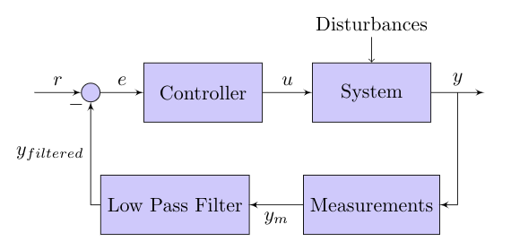
The block diagram of the control loop is:
The oscillations have been reduced but not achieved a satisfactory level. Is there any way to modify these controllers in a way to affect these oscillations and reduce them ? Would a PID-controller perform better due to the existence of the derivative of the error ? Or should I design a better filter for the noise reduction which should also be fast (because the system is functioning in real time) enough ?
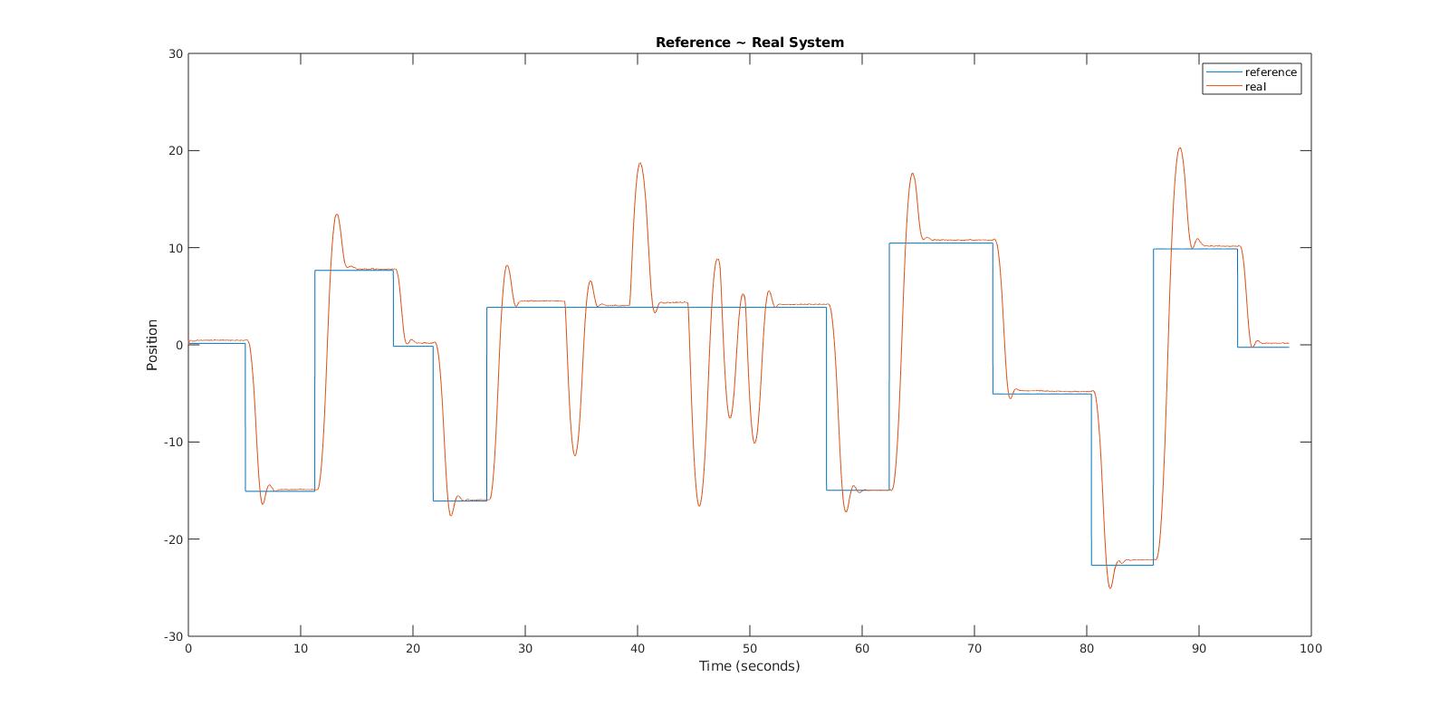
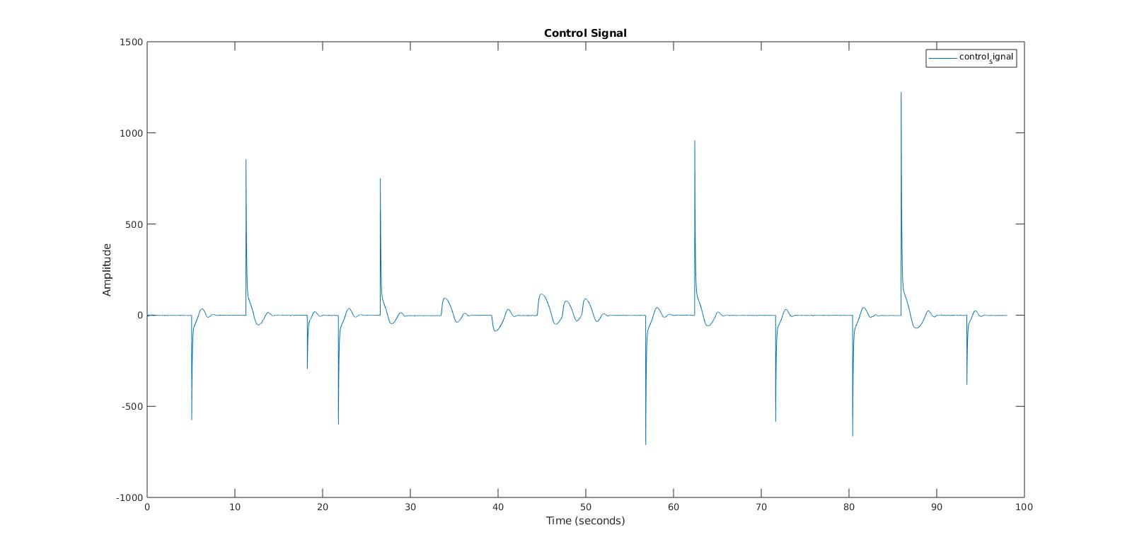
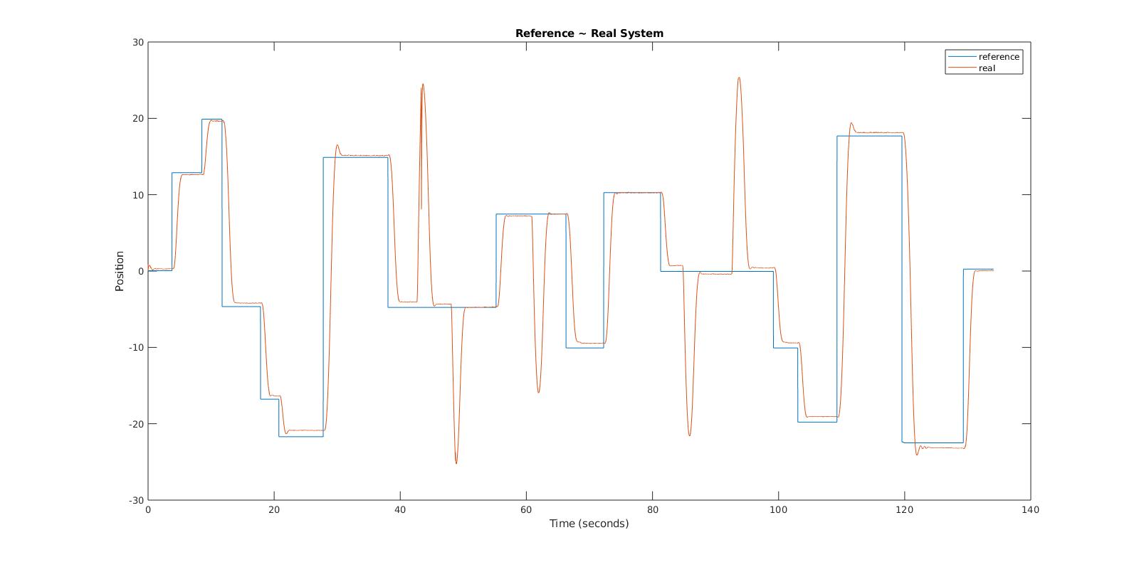
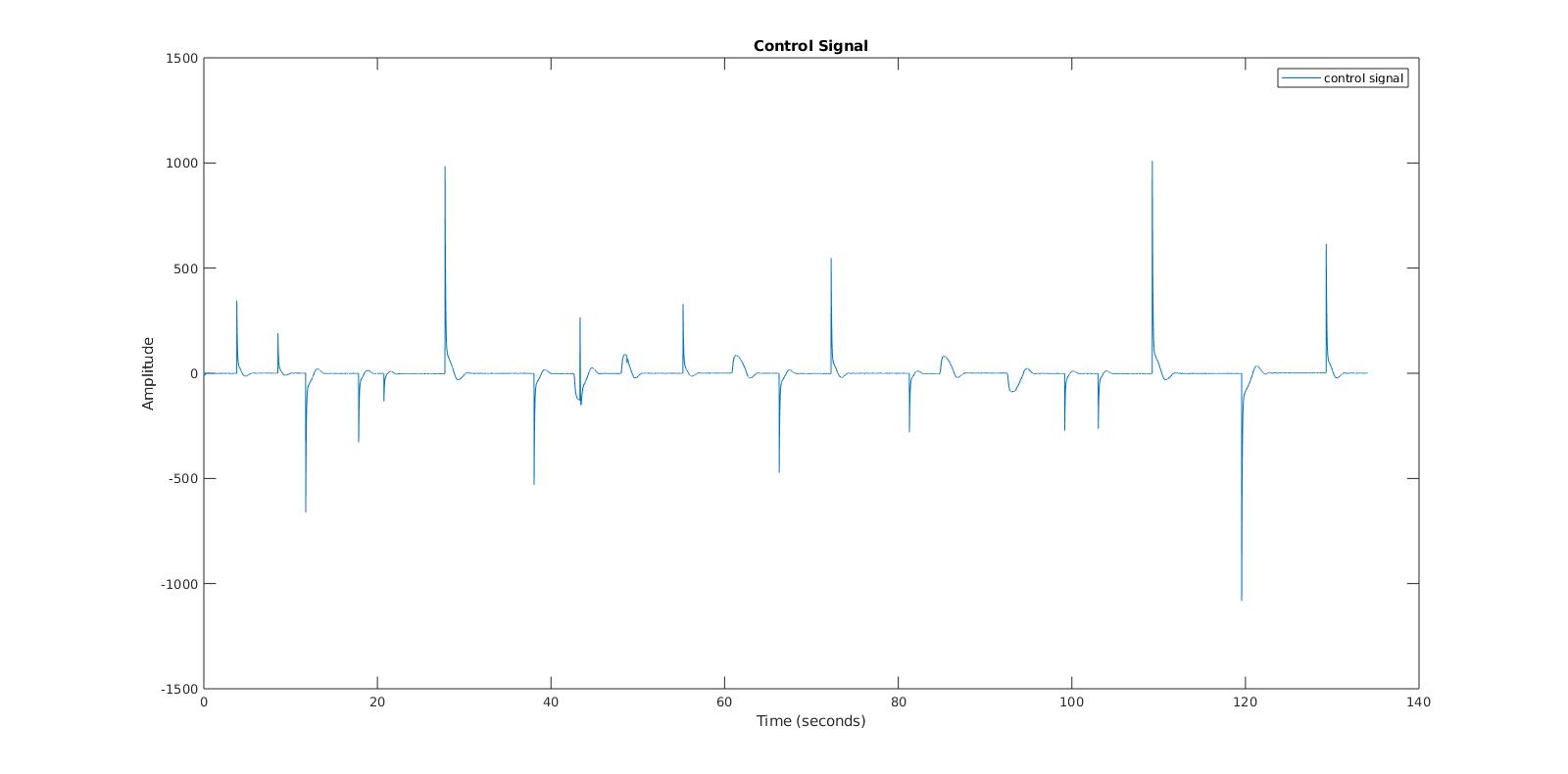
I place some plots for two different cases (PD-controller gains) where the actual position (output) is shown compared to the reference and the control signal. Note that the sudden changes to the real system's output are due to external disturbances I apply in order to check if the system goes back to the reference.
- First Case ($\ K_p = 3.9352 $ & $\ K_d = 2.248 $):
- Second Case ($\ K_p = 2.3536 $ & $\ K_d = 1.6423 $):
