9
$\begingroup$

The Question:

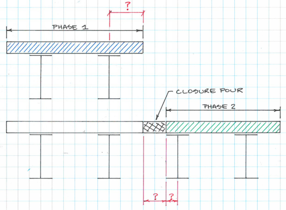
Where should a closure pour be located relative to centerline of girder and how should the closure pour width be detailed/designed?

And now, a little background:

When designing a steel girder bridge using phased construction with dead load deflections exceeding 2", my state (Nebraska, USA) requires a closure pour. No guidance is provided on how to locate or design the closure pour. As a point of reference, I'm dealing with a 100 ft span and a 44" deep girder.

I've done moderately extensive Googling and found varied suggestions. Align the edge of the pour with centerline of girder. Don't align the edge of pour with centerline of girder. 2' minimum width. 3' minimum width. And an interesting suggestion from Nevada DOT (p. 16-10) that:

The required width can be estimated by considering the closure pour to be a fixed-fixed beam and by limiting the stresses in the concrete to the cracking stress.

Which sounds quite promising, though I haven't fully digested the particulars of execution.

Where my noggin really starts to hurt is when I start thinking about how my girder deflections will be affected by phasing and a closure pour. Say my girder has a tributary deck width of 96" in the finished condition. But during phased construction, only the left 2/3 of this deck will be poured. Do people execute a series of analysis runs looking at all the intermediate conditions and the progressive deflections/stresses?
enter image description here

$\endgroup$
0

1 Answer 1

1
$\begingroup$

This isn't going to be a very authoritative answer, but its the best I've got.

I can give you no evidence to why this is good practice, but at my previous job where I used to work with such deck closure pours, we had a standard detail, with the pour width equal to 15 cm (approx. 6") for slabs usually around 22 cm (approx 8.5"). Where that value came from or what benefits or drawbacks it has, however, I don't know.

Regarding the location of the pour, we didn't really think too much about it. We'd never put it glued to a beam, though: that just makes your life more complicated since the load profiles for the "Phase 2" beams will be radically different (and can cause your "Phase 2" to be slightly tilted, since one beam will deflect more than the other). We tried to have a somewhat symmetric "Phase 2" structure, even if that implied in a slightly larger final span between the "Phase 1" and "Phase 2" beams.

Thinking about where to put the pour, however, I'd wager a good position is around one fifth of the total span between the "Phase 1" and "Phase 2" beams. I come to this considering that slab as a fixed-fixed beam (which implies I'm considering the slab to be one-way). Such a beam has, under uniform load, zero bending moment approximately one-fifth of the span away from the supports (more precisely, $\dfrac{1}{6}\left(3-\sqrt{3}\right) \approx 21.13 \%$). This should reduce the stress directly over this spot.

enter image description here

Another option would be to see where the lanes of the final bridge will be and put the pour as close to the center of one of the lanes as possible: this should effectively eliminate the risk of having heavy vehicles driving with wheels directly over the pour (motorcycles probably aren't much of an issue).

Regarding how deflections are taken into account when doing the pour, that's actually a really good question to which I don't have much of an answer. It's worth pointing out, however, that at such a moment your bridge will be under a significantly reduced load. If the bridge is entirely brand new, it will probably be completely closed and therefore only under its own dead-load (plus some load from the work being done on the bridge, but that's minimal). This means that, should the tributary areas of load going to each of the beams in "Phase 1" and "Phase 2" be somewhat similar, the phases should actually deflect similarly as well, in which case you won't have much of a problem. If you're reinforcing an existing bridge, however, you may well have to leave at least one lane open in the "Phase 1" segment. This will lead to variable deflections between the different phases (not to mention vibrations which I've heard make these pours very problematic), but I honestly don't really know what to do about it.

$\endgroup$

Your Answer

By clicking “Post Your Answer”, you agree to our terms of service and acknowledge you have read our privacy policy.

Not the answer you're looking for? Browse other questions tagged or ask your own question.