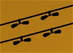
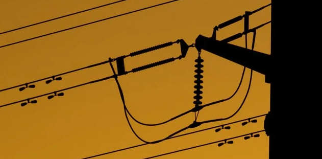
In order to supplement @fred_dot_u's answer and add a few details on the nature of the problem that these devices address I'll add a bit of additional material.
For a description of a numerical model of how Stockbridge dampers work and ANSYS simulation results, see for example Aeolian vibration of a single conductor with a Stockbridge damper, Oumar Barry, Donatus CD Oguamanam and Der Chyan Lin, Proc IMechE Part C: J Mechanical Engineering Science, 227(5) 935–945, DOI: 10.1177/0954406212452064
Also, from J-L Lilien's Power Line Aeolian Vibrations.
Aeolian vibration is a low amplitude (conductor diameter) high frequency (5 to 150 Hz) phenomenon. Aeolian vibration is one of the most important problems in transmission lines because it represents the major cause of fatigue failure of conductor strands or of items associated with the support, use, and protection of the conductor. In this phenomenon, conductor strand fatigue failures occur at the suspension clamps or at the clamps of the other devices installed on the conductor such as spacers, spacer dampers, dampers and other devices.
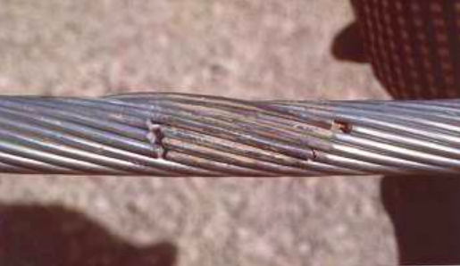
Fig 2.1 typical broken strand due to aeolian vibration after removal of suspension clamp.
Forces induced by vortex shedding are the cause of this type of vibration (Blevins1990, Buckner 1968, Claren et al 1969 & 1974).
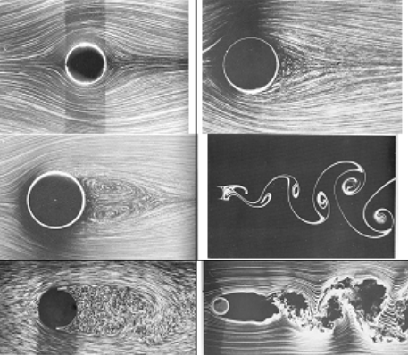
Fig 2.2 Flow visualization; identification according to (row, column): (1,1) R=1.1 (Taneda), (1,2) R=9.6 (Taneda), (2,1) R=26 (Taneda), (2,2) R=140 (Taneda), (3,1) R=2000 (Werlé & Gallon), (3,2) R=10000 (Corke & Nagib)
The fatigue mechanism
The fatigue in power line conductors are caused by fretting between different layers
of strands at their contact area (fig 5.1). Some cracks appear and propagate. The
stick/slip elliptical contact area is depending on the radius of curvature taken by the
conductor. During alternating bending stress (due to oscillations) that radius of
curvature is changing continuously. It is particularly important near clamp ends at the
last point of contact.
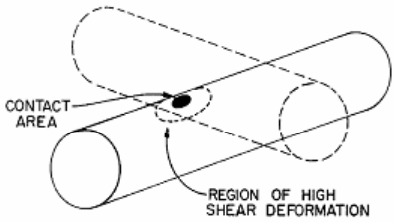
Fig 5.1 the inter-strand contact area where first crack may appear (Epri-1979)
From Aeolian Vibration Basics
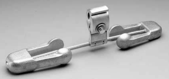
Figure 14 – VORTX™ Damper
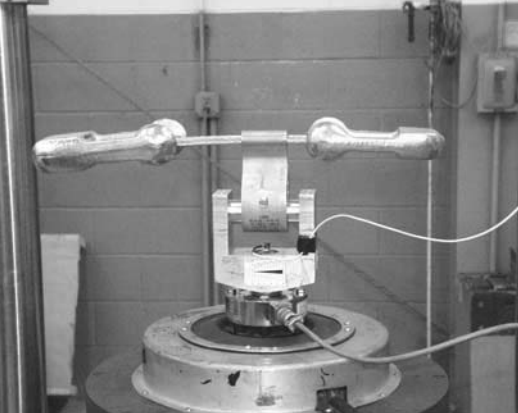
Figure 16 – Damper Response Test Set-Up
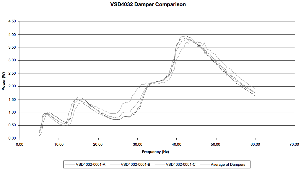
Figure 17 – Damper Response Curvee
Figure 17 shows the power (in watts) delivered to the damper by the shaker (vertical axis) over a range of frequencies. The results are shown for three of the same damper design, along with the average. This plot shows four distinct peaks in the power curve. These represent the resonant frequencies of the damper weights. Each weight has two resonant frequencies: one where the furthest end of the weight has the maximum movement, and the other where the end nearest the clamp has the maximum movement (higher frequency). The VORTX Damper shown in the curve has two different weights, each with different resonant frequencies, which accounts for the four peaks in the curve
