5
$\begingroup$

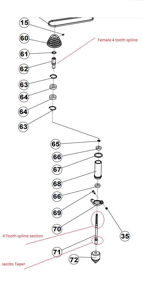
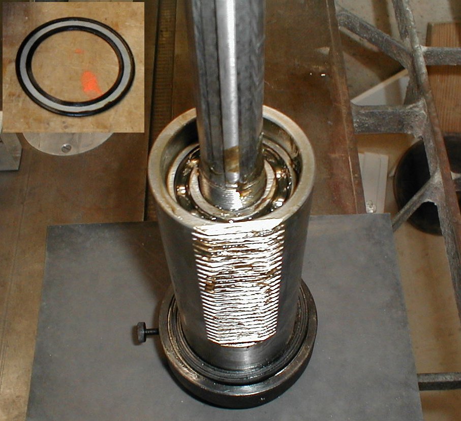
I only have basic metal fabrication tools and do not own a mill or a lathe, but would like one. I took apart my cheap drill press to study whether or not I can convert it into a milling machine. The spindle features a 4 tooth 9mm x 9mm tooth male splined section that mates with a female splined bushing press fit into the pulley's bore (see parts numbers 62 and 71 in diagram). The entire spindle fits inside the quill tube (see part 68) creating the quill assembly (see photo below). The spline allows the spindle to extend downwards and upwards in the head casting while also allowing the spindle to rotate with maximum torque.

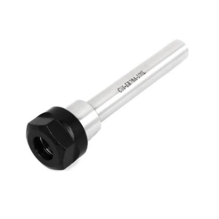
Currently, I am considering replacing the entire spindle with an 16mm O.D. ER20 tool holder. This will give me a more ridgit hold on the cutting tool as Jacobs Taper cannot handle axial forces required for milling. I am also planning on replacing the existing bearings with either angular contact bearings or tapered bearings.

I would like to maintain the quill's retract and extend mechanism. To do this, I will have to somehow jointhe end of the ER toolholder to a splined shaft that will fit in the female end. Currently, I can't seem to find any off the shelf spline to 16mm coupling. I am not even sure what they are called.

Are there any solutions for coupling or attaching a spline shaft to a plain old shaft? What is it called and do they exist? Finally, I am not completely married to using a spline drive mechanism in order to extend and retract the quill, so I welcome any suitable alternative mechanisms. I saw a ball spline, but wasn't sure if it works the same way as the existing mechanism.

Here's a photo of a similar quill:

enter image description here

enter image description here

enter image description here

$\endgroup$
2
  • $\begingroup$ Would it be possible to do a sketch of the front view of where you want the spline shaft to end and the transition to the tool holder to happen? $\endgroup$
    – Ethan48
    Commented Jun 16, 2016 at 16:59
  • $\begingroup$ OK, I modified my question to be more explicit. I also included a diagram. Hope it helps. $\endgroup$
    – user148298
    Commented Jun 17, 2016 at 0:10

4 Answers 4

1
$\begingroup$

In general, I would warn you that you aren't likely to get very good rigidity out of this system because by maintaining the quill mechanism and adding the length of the tool holder plus an extra joint (of any type) you are adding more cantilever to what sounds like already fairly sloppy tool. In addition, be warned that the manufacturer of the tool certainly won't endorse any project like this and any joint you implement yourself may fail, so you're going to be spinning a pretty heavy piece of metal pretty fast at your own risk. Personally, I wouldn't recommend it.

That said, you asked about ways to couple the spline shaft with the tool holder's cylindrical end, here are some options:

Firstly you could buy an adapter. Spline shaft adapters are made, but usually only for much larger shafts. In addition, I'm not sure if that spline profile will be standard or specific to your drill press manufacturer. Other people will make you a custom spline adapter, which may be expensive but would get the job done. Most reasonably equipped local machine shops could also make an adapter. The problem with connecting spline-to-spline is that with the cutting forces, you'll have significant axial and radial forces to resist. Splines are good at transmitting torque, and reasonable at resisting radial force, but don't resist axial forces at all. For that reason, pick a spline adapter design where the female spline rigidly cplamps to the spline with a thru-bolt, not one of the designs that only has a set screw.

Another strategy would be to try to develop as much clamping force on the outside of the spline shaft as you can, completely forgoing any contact with the radial faces of the spline. To do this you could use a regular shaft coupling like this or this. Standard rigid shaft couplings with different sized bores at each end are rare though, so you may still need to get one made custom. It is common to find couplings where one end is a finished bore and the other end is unfinished to allow you to bore it out yourself, but I haven't found any small enough for your application. If you do decide to do this, the bore needs to be cut by a machinist on a lathe, don't attempt to use the drill press for it.

The last option, though I'm still not confident you could find parts small enough is a taper lock shaft coupling like the Fenner RM12 shown here or the Climax C600M-9 shown here. They have compatible sizes for 9 mm and 11 mm shafts, but don't seem to make it up to 16mm in one go, so you may still need one special bushing. These type of couplers work on a taper principle, much like a collet and produce probably the strongest and most rigid clamping force of any of the options here. Because these systems are modular (the inside tapered bushing works with multiple flanges) you are most likely to be able to find the sizes you need as stock parts. I have not searched exhaustively for suppliers that may stock your specific sizes.

Overall, I think that this is a very risky idea and may well result in failure or even injury. I suspect that to join such mismatched shafts you will need a part custom-machined, which as you know is not a cheap proposition. If you do need something custom machined, you might as well get a whole new shaft machined that has the 9mm spline profile and the tool holder itself, but by the time you pay for that, you probably could have bought a small used mill with much less hassle and risk.

There are of course other options like drilling a through hole radial to the shaft and inserting a bolt or pin, or welding the two shafts together, but neither will give you nearly the rigidity or concentricity you need, and they are likely even more dangerous that the other options.

$\endgroup$
6
  • $\begingroup$ Hmm. Nice. How about a ball spline? There are some pretty small sizes and although they are overkill, I've seen some smaller diameter ones. I can't tell if they transmit radial torque or if they are just another style of linear bearings. $\endgroup$
    – user148298
    Commented Jun 17, 2016 at 13:09
  • $\begingroup$ Are you trying to scare me or is there a real danger? What can go wrong, specially when making light cuts. $\endgroup$
    – user148298
    Commented Jun 17, 2016 at 13:16
  • $\begingroup$ They can handle radial loads, but they won't be designed to meet the same spline shape you have - you would need a custom spline. For the size and loads of the drill press, a plain old spline with sliding friction will work better. Ball splines are very sensitive to contamination so machining is not a good place for them unless they are completely shielded. $\endgroup$
    – Ethan48
    Commented Jun 17, 2016 at 13:18
  • $\begingroup$ There is real danger. If the join fails, not only the cutting tool but the tool holder can go flying. Because cutting has forces in many directions and causes vibration, it is a hostile environment for any joint not specifically designed with it in mind. You would need to check regularly that nothing had come loose or started cracking. $\endgroup$
    – Ethan48
    Commented Jun 17, 2016 at 13:20
  • $\begingroup$ Well. remember that the spindle will be completely enclosed inside the quill and head casting. So it won't be exposed to the elements. If it does come apart, it will be inside the either the quill or the head casting. I plan on running it on vey low speeds (under 500 RPMs) which is my primary purpose for doing this. $\endgroup$
    – user148298
    Commented Jun 17, 2016 at 13:22
1
$\begingroup$

The really quick and dirty solution: weld the current chuck to the current taper. That will ensure it won't come flying off. Then you can do light milling and start making parts for a stronger/better machine without having to buy any new bits for your drill press!

I wouldn't bother throwing a lot of money at this as drill presses are generally not rigid enough to make 'good' milling machines. Any welder should be able to put some large tac-welds (I'd do four 90 degrees apart) on that in about 5 minutes which would prevent it ever coming off (be careful about doing too much welding as you don't want to introduce too much heat into the part).

$\endgroup$
4
  • $\begingroup$ It is near impossible to weld something concentric enough to work well. Even if you can live with the inaccuracy, rotating an off-center mass at high speed is even more dangerous than the other ideas proposed. $\endgroup$
    – Ethan48
    Commented Jun 21, 2016 at 13:20
  • 1
    $\begingroup$ No no, I don't mean weld the tool holder to the shaft. I mean weld the current chuck to the taper. The OP said the reason he couldn't use it is because the chuck is held on by a Jacob's taper which can't take lateral load and could fly off. Solution: weld chuck to taper so it won't come off while ensuring it's still cocentric (or as cocentric as it ever was) $\endgroup$
    – m4p85r
    Commented Jun 21, 2016 at 22:02
  • $\begingroup$ That's worth a try if the tool is otherwise trash, but there is significant risk of seizing up the chuck with heat stresses - there isn't much clearance in any of those moving parts. It's also not too likely that both pieces of the taper are made of an easily weldable steel, but they might be. $\endgroup$
    – Ethan48
    Commented Jun 21, 2016 at 22:57
  • $\begingroup$ Ah a couple of large tack welds won't seize the average drill chuck. Those things are pretty sloppy. I agree that it's not something I'd do on machinery I valued highly, but by the sounds of it this is an interim machine so he can make slightly better parts. Ah it's steel, it'll weld ;P well enough for this purpose anyway. $\endgroup$
    – m4p85r
    Commented Jun 22, 2016 at 6:49
0
$\begingroup$

This is general advice rather than a direct answer but given the circumstances you have described my feeling is that this sort of modification may be more trouble than it is worth.

Part of this is that a drill press doesn't necessarily need to be all that rigid in order to work well. With sensible work holding you can get perfectly acceptable results for general drilling with even quite a basic machine and you may very well find that any gains in rigidising the spindle are lost by the overall tolerances of the machine as a whole.

Even quite an expensive pillar drill is not by any means the same thing as a vertical mill.

Apart form anytime else if you are prepared to do this level of modification you might well be better off spending your time refurbishing a small used lathe as that will probably give you more benefit in the long run for similar effort.

$\endgroup$
1
  • $\begingroup$ I am trying to build a mill not another drill press. The current drill press has a Jacobs tapered end that holds onto the Jacobs tapered chuck. It is unsuitable for milling since it cannot handle axial forces, which can send the chuck flying across the room. It has never happened to me, but I've read it in countless places. $\endgroup$
    – user148298
    Commented Jun 16, 2016 at 18:37
0
$\begingroup$

I would tend to agree with Chris Johns on this one - it's probably not a great use of your time and may not provide satisfactory results - but that's not what you asked...

To directly answer your questions:

Are there any solutions for coupling or attaching a spline shaft to a plain old shaft? What is it called and do they exist?

Yes, there are. A press-fit, or interference fit, may be a suitable means of attaching the two components.

If you're not familiar with the concept, a press fit (aka interference fit) means you press a pin into a hole that is slightly smaller than the pin (creating interference between the components which holds them together). In the case of metal-to-metal were talking a size difference of few tenths' of a thousandth of an inch [.0001] to a few thousandths [.001] of an inch.

If you provide more information regarding the materials of construction (presumably some sort of hardened tool steel for the shaft, not sure about your collar) and actual dimensions (actual meaning you measured the parts with a micrometer, or other suitable measuring device, and not the nominal dimensions provided by the manufacturer or parts description) then you could use an online fit calculator such as this one provided by Engineers Edge to get an idea of the interference needed - maybe look to the FN5 class for example.

I'm suspecting you're going to need a significant interference to withstand the loads expected, so you'll probably need a hydraulic press or a good source of heat, or maybe a combination of the too.

Again, if you know the material of construction, you can use the coefficient of thermal expansion to determine the temperature change necessary to cause the female member to expand large enough to slip the male member in, and then when it cools and contracts it will create the interference necessary to hold the parts in place.

Another option you might consider, is that you can press fit the pieces together (I recommend the shrink fit method above to maintain concentricity) and since this is a splined shaft fitting into a round hole, you may be able to braze the shaft to the coupling (filling in the gaps in the teeth with brazing material) which would be extremely strong. Again without knowing more about the base materials I don't know if this is a suitable suggestion, but it's worth considering. Many cutting tools used for milling operations which have carbide inserts are brazed, and it's proven to be a reliable and strong connection for the job.

Standard disclosure: you should consult an engineer experienced with this type of application (someone specializing in machine design, or machine maintenance might be a good place to start) before taking numbers off some website or the words of some guy who doesn't have all the information about the application. For one - the numbers suggested on the site I linked to are based off an ANSI standard that provides recommendations for common applications of holding a round pin in a round hole - none of which describes your application. And for two - you're playing with some pretty large forces and heavy loads in a milling operation, and a catastrophic failure could send an extremely sharp large chunk of carbide, cobalt, or high-speed-steel straight at your face, eye, throat, or child-rearing organs which would not be very fun at all.

Finally, I am not completely married to using a spline drive mechanism in order to extend and retract the quill, so I welcome any suitable alternative mechanisms. I saw a ball spline, but wasn't sure if it works the same way as the existing mechanism.

Bridgeport mills typically use an R8 quill.

I don't know if it's feasible, but if you're going down this road you might look at adapting one of these to your drill press.

Lastly - my personal opinion only - is that the amount of time and money you'll spend on this project, which may or may not have a good outcome, is not going to be worth it. Have you considered just purchasing a used bridgeport (or cheaper chinese knock-off) mill? I'm not sure where you're located, but I just did a quick search on craigslist and in my area there are at least 5 ad's for 2500 USD or less, and a couple for 1200 USD or less. I would seriously consider what you want to do with your mill, and decided when it's worth spending the money on a proper machine, and until then, you can always outsource your milling work to a local shop or even an online company like rapid-machining.

Best of luck to you! -Steven
$\endgroup$
5
  • $\begingroup$ It is nearly impossible to make something with a tight enough tolerance to press-fit or interference fit without machine tools. Also, this is already the principle of operation of a Jacobs taper, which the original post states is not secure enough for them. $\endgroup$
    – Ethan48
    Commented Jun 23, 2016 at 13:11
  • $\begingroup$ My answers address the questions quoted - not the entire post by the OP, which I would argue is not complete enough to answer definitively. For example, he's provided no information on the materials of the shaft/coupler, the actual OD of the shaft and ID of the coupler, what about clearance to the housing, is the drill press belt driven (good luck milling if it is...), etc. We don't know what he intends to mill in the end (size, material, required tolerances to be held), his budget and timeline for the project, etc. I attempted to answer the answerable questions. $\endgroup$
    – CBRF23
    Commented Jun 23, 2016 at 14:32
  • $\begingroup$ I would also disagree - he has a drill press. I assume it's of a good quality and robustness if he intends to mill with it. Given these assumptions he could use the drill press to drill and ream the hole as needed. There's also the option of outsourcing the work to a local machinist or even somewhere like rapid-machining.com. Creating a hole is not an insurmountable obstacle to this project. Also a press fit provides superior resistance to side-loading compared to a Jacobs taper. Add the recommended brazing step and it's not even a comparison. $\endgroup$
    – CBRF23
    Commented Jun 23, 2016 at 14:36
  • $\begingroup$ Err, let's not get into an extended discussion in the comments here, but if you look at the whole question it is clear that the drill press is belt driven, and for the record so are many if not most manual mills. As for reaming a clean enough hole to press-fit on a drill press with a chuck, I suppose the proof is in the pudding! $\endgroup$
    – Ethan48
    Commented Jun 23, 2016 at 14:50
  • $\begingroup$ I see that now - in the parts image :) I would agree - it's unlikely to be perfectly concentric, but likely to be good enough for this application. I wouldn't expect great results out of this project. So far I think the best answer is the one suggesting to weld (or braze, might work also) the chuck to the taper. $\endgroup$
    – CBRF23
    Commented Jun 23, 2016 at 20:19

Your Answer

By clicking “Post Your Answer”, you agree to our terms of service and acknowledge you have read our privacy policy.

Not the answer you're looking for? Browse other questions tagged or ask your own question.