0
$\begingroup$

To explain the situation, I am creating a site plan (using Autocad 2022), I have a building that is angled within a complex property. The 4 corners of the building are dimensioned to a property line(PL). What I did, was offset a line from each of the PLs that had a dimension attached to it at the appropriate value. I now have 4 lines at different angles and I need each corner to be touching one of the lines. The align tool only works for 2 reference points really and even that does not do so well at attaching to 2 points. I could manually play around, but there has to be some what to select a point and a line it should attach to for each of the 4 corners.

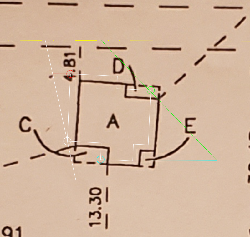
Update: Here is a snip of one of the situations I am trying to resolve. I need the corner with the red circle to sit somewhere on the red line, the corner with the green circle to sit on the green line, and so on for the cyan and white. I believe there should only be one way that all of the corners can be sit on their respected line at once. enter image description here This image shows after I have already tried to quickly do this manually.
Anyone have any advice on this situation?
$\endgroup$
8
  • 2
    $\begingroup$ Post a properly cropped screen grab. This doesn't seem to be AutoCAD specific question - it seems to be a basic drafting problem. $\endgroup$
    – Transistor
    Commented Feb 6, 2022 at 9:14
  • $\begingroup$ Agree with @Transistor that you really need to post a sketch, screen capture, or picture of the problem in order to receive some good advice. From the basic sounds of things, I would be looking at your resulting offset rhombus and placing a rectangle with one corner where you want it. I am guessing I would probably then rotate the rectangle to align with one of the offset lines. I would then either stretch or scale it to get the corner of the rectangle on the offset line to where it needs to be. I would then stretch the remaining to rectangle corners to where they need to be $\endgroup$
    – Forward Ed
    Commented Feb 6, 2022 at 13:15
  • 1
    $\begingroup$ Also, it's not really clear what the end result should be. Are you trying to find the maximum size building you can fit in the site or do you have the size of the building but have some other constraints? $\endgroup$
    – Transistor
    Commented Feb 6, 2022 at 13:29
  • $\begingroup$ I'll try to get a snip later today, but using the property lines that Forward Ed's answer showed, imagine those lines are setup as the distance lines to the 4 corners of the building, the building is existing and rectilinear with all 90 degree corners. I need to rotate the building so that each corner lands within the respected line. For this instance it is crucial as the goal is to add in an addition to the existing building but avoiding an easement that runs through the property. Hopefully that helps, I'll try to add an images later today. $\endgroup$
    – Markitect
    Commented Feb 6, 2022 at 14:59
  • $\begingroup$ One more note, I have an existing survey pdf with everything dimensions and labeled, but no CAD to use. And the drawing is not to scale/accurate for the dimensions specified so I can't just trace the pdf. $\endgroup$
    – Markitect
    Commented Feb 6, 2022 at 15:01

1 Answer 1

0
$\begingroup$

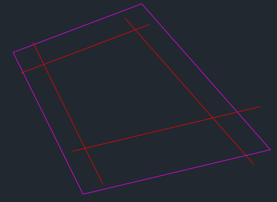
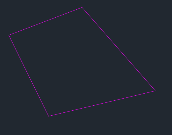
Lets assume for now that your property line in magenta are laid out as followed:

enter image description here

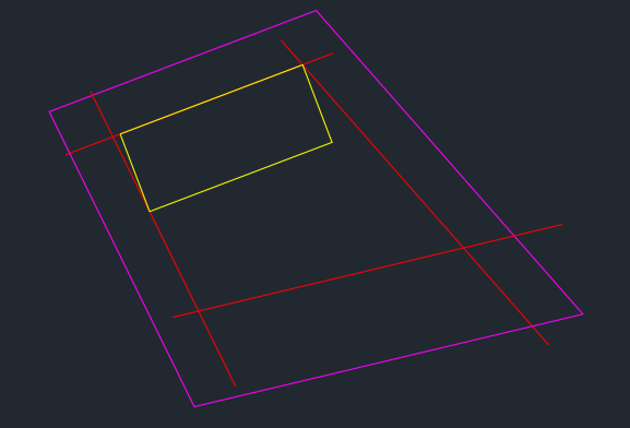
Now we offset the property lines to define a boundary the building has to fit in. Lets also assume that the lower property line is your street frontage and therefore requires a larger offset (mainly so it is not all equal offsets). The re line represent your parallel offsets:

enter image description here

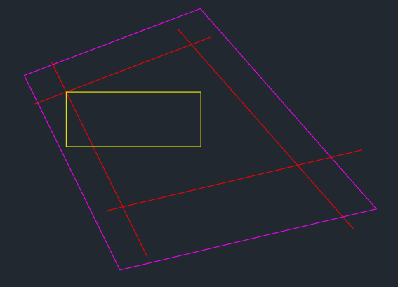
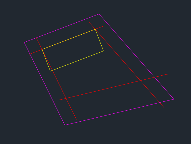
Depending on what your ultimate goal is with the building placement your solution may vary from this point. I would start by drawing a rectangle with the corner coincident one of the other corners. Lets take the top left:

enter image description here

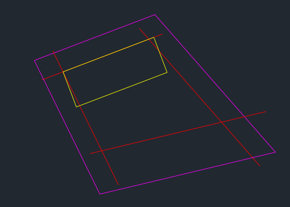
I would then rotate the yellow rectangle with the top left corner as my base point. I would rotate using the reference option. My reference line would be the two end points of the top rectangle. I would then choose any point on the top red offset line to rotate to. When done properly it should align as follows:

enter image description here

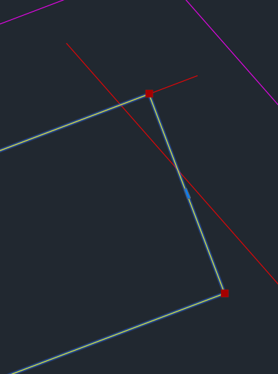
Now note in this situation the top right corner of the rotated rectangle is now outside the offset line. It could also have been short of the property line. To get this in the right position I would select the rectangles two right corner grip points at the same time and drag the top right one to the intersection of the two red offset lines:

enter image description here

If done right it should look like this:

enter image description here

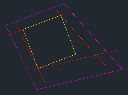
I would repeat this process for the left side, except this time you want to drag the two left corner grips such that the bottom left corner goes to the intersect of the left red offset line the the bottom yellow rectangle line. when done right it should look like this:

enter image description here

Now depending what your needs are, you may need to have the building touching front and back offset lines. Just repeat the steps above as needed and you can get something that looks like the following:

enter image description here

There are multiple solutions on how to size the building. Try a few different placements and see which one suits your needs. It will also give you good practice with CAD.

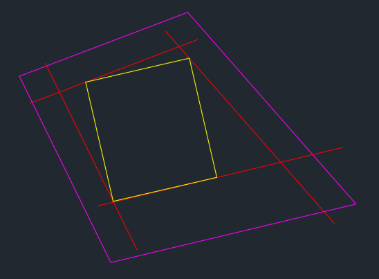
Here is an option with all four corners on at least 1 line:

enter image description here

Note: For this example it is not the only solution.

$\endgroup$

Your Answer

By clicking “Post Your Answer”, you agree to our terms of service and acknowledge you have read our privacy policy.

Not the answer you're looking for? Browse other questions tagged or ask your own question.