7
$\begingroup$

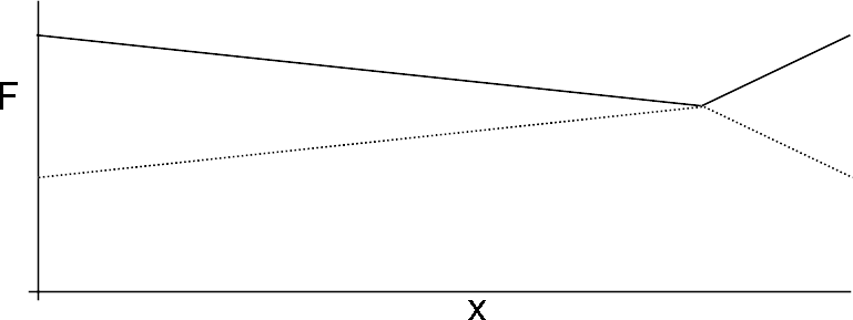
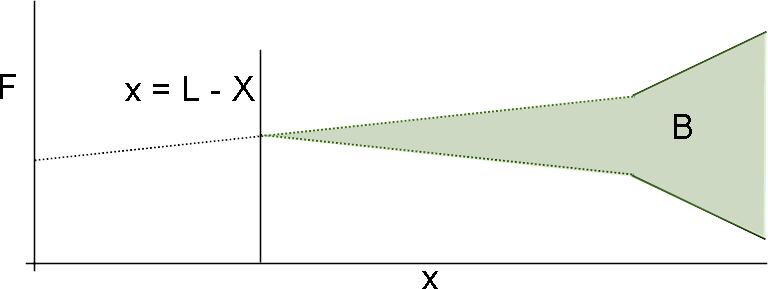
Post-tensioned prestressed concrete beams suffer from a multitude of losses. When jacked, they suffer friction losses and their tension diagram is, for example (to simplify the drawing, I'm using the linearized version of the friction loss equation here. It also goes without saying this is all horribly out of scale).
enter image description here

This diagram obviously represents a beam prestressed from both ends. Also, the cable's path is clearly non-symmetric, with the right side probably being excessively curved, while the left is probably far smoother. The dotted lines simply demostrate what the digram would be if the cable were prestressed from only one end.

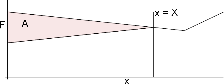
When the cable is then anchored to the concrete, the anchorage slips into the concrete, causing losses. These losses, however, are limited by friction to an area around the anchorage since the cable has by this time already been grouted. We can define the point where anchorage slip losses end as $X$. An anchorage slip of $\delta$ is by definition equal to $$ \delta = \int\limits_0^X\Delta\epsilon_p(x) dx = \dfrac{1}{E_p}\int\limits_0^X\Delta\sigma_p(x) dx\\ \therefore A_pE_p\delta = \int\limits_0^X\Delta F(x) dx $$ where $x=X$ is defined as the point where the anchorage slippage losses end.

We therefore have a relation between the constant $A_pE_p\delta$ and the area between the force diagram before and after these losses. All we need to do now therefore is find $X$ such that the equality is satisfied. For simple cable paths there are some analytical methods, but they aren't relevant to this question.

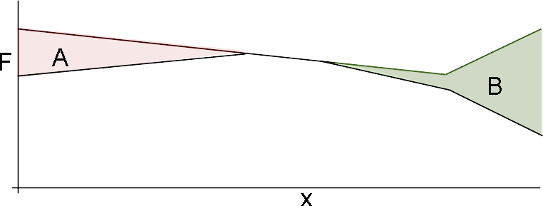
If the slippage losses are small enough, we just need to calculate the losses for each side, such that $A = B = A_pE_p\delta$:
enter image description here

That case, however, is quite simple. From now on, I am less sure of whether what I'm saying is correct, so please correct me if I'm mistaken.

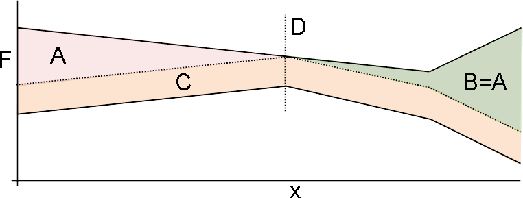
If, however, the losses are such that one side interferes with the other, it is easier to find an area $A+B+C = 2A_pE_p\delta$, where $A=B$, point $D$ is defined as the point where the losses first encountered each other and $C$ is simply a uniform loss along the entire cable that occurs once point $D$ is reached:
enter image description here

My first question is: is this a correct calculation of the anchorage slip losses in case the anchorages are released simultaneously? Is there a simpler (but generic) method?


The other question is what if the anchorage slippage losses are not simultaneous?

For the left side we may find $X$ and reach the following result, where the area $A = A_pE_p\delta$: enter image description here
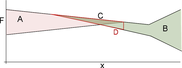
For the right side I'd consider calculating the losses on the friction diagram considering that the cable was only pulled from the right side, so we get the area $B = A_pE_p\delta$: enter image description here
We can then throw that on top of the results for the left side and get the following, where $C$ is the area overlapping with $A$ and $D$ is the part of $B$ after the end of $A$ ($C$ is contained within $D$ which is a part of $B$): enter image description here
So, what now?

Should the area $D$ be transposed to accompany the force profile after the left anchor settled? enter image description here
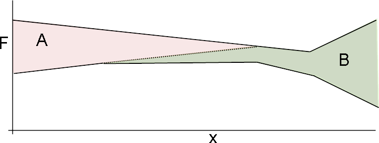
Is this correct? Is there an easier (but generic) method to solve this case as well? Throughout this, I've made use of the assumption that the friction (and therefore anchorage slip) losses are linear, which they are not. Other than the mathematical headache of dealing with exponential equations, is there anything here that simply won't work using the losses' true exponential form?

$\endgroup$
0

1 Answer 1

-1
$\begingroup$

Apologies that you didn't find the article informative, I figured the simplified equations for losses without stiffness matrices and polynomial derivations would be helpful as well as thinking of the structure as a string. I'm sure you're aware of metal beams being simplified to $f=Kx$ where $EA/L$ is the spring constant, however to incorporate a realistic model you have to take creep, elastic deformation, etc I'm sure you know all that. I suppose I'm confused as slippage occurs at the end connections. Simply $PL/EA = \Delta$ or slip of anchorage (P is prestress etc). In your case you need nodal functions. You are looking at a simple beam using two force diagrams, am I missing something? Use $f=\int B^T \tau \text{d}V$ to find the nodal forces which have to satisfy the basic conditions for elemental analysis. First you need the stress, which I'm sure you know. Your area calc is confusing as your $K$ matrix should be an integration of the derivatives of the area function at the very least i.e.

$$\int_L E A(x)dx/L^2\begin{bmatrix} 1 & -1\\ -1 & 1\end{bmatrix}$$

for a simple beam, then find $d^T f= F1x + F2x...$ etc. Remember $\text{strain} = Bd$, and for shape functions you'll most likely have to use at least polynomial expressions, but the derivative matrices make it easier. Also, if you want to deal with creep have fun with Maxwell's equations! Simple answer, simplify and ask any specifics you run into.

$\endgroup$
7
  • $\begingroup$ I just read quickly through the entire article, but I failed to see its relevance to my question. It makes multiple simplifying assumptions such as single-curvature tendons, which allows it to know that the space available for the anchorage losses from each side is equal to half the span. My first question deals with the more general case where this isn't known a priori (which is why I chose such an asymmetrical diagram). It also makes no mention to non-simultaneous jacking, which is the essence of my second question. If I missed something, please edit your answer explaining it. $\endgroup$
    – Wasabi
    Commented Dec 31, 2016 at 11:57
  • $\begingroup$ Answers which solely provide a link without an explanation that addresses the question are of little value. Unless improved upon, this answer will mostly likely be deleted. Please provide some detail to your answer. $\endgroup$
    – Fred
    Commented Dec 31, 2016 at 12:39
  • $\begingroup$ I'll try to get into time dependencies later $\endgroup$ Commented Dec 31, 2016 at 14:24
  • $\begingroup$ After your edit, I have no idea what your answer has to do with my question. This question has almost nothing to do with beam stiffness. The $\delta$ in my equations isn't the beam's deflection (which is what's calculated by the equations in your answer), but the anchorage slip of the prestressed cables. This value is a known constant (or assumed as such) for different anchorage systems. When you say $PL/EA = \delta$, you seem to be confusing anchorage slip with concrete's elastic deformation (assuming simple axial compression, without any eccentricity between the cable's and beam's axes). $\endgroup$
    – Wasabi
    Commented Jan 2, 2017 at 10:31
  • $\begingroup$ If you don't recognize the relationships presented for conceptual consideration I can't help you. You know that slippage is fundamentally related to creep, pre stress and deflection yet you think im talking about concrete? Look at your equation vs mine. Yes you have to transpose the forces. $\endgroup$ Commented Jan 2, 2017 at 12:33

Your Answer

By clicking “Post Your Answer”, you agree to our terms of service and acknowledge you have read our privacy policy.

Not the answer you're looking for? Browse other questions tagged or ask your own question.