0
$\begingroup$

I am very much confused finding the time constant and DC gain for the below step response. The idea is to find PI gains for speed control and I am following this tutorial online Tutorial Link

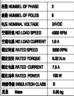
Motor specifications

enter image description here

Below is the open loop step response when a 10 V is applied across the DC motor. The battery is of 26 V, which means that a PWM duty cycle of 38% or 0.38 (10/26). The X-axis is time(seconds) and the y-axis is Gear box output shaft RPM. Initially it stayed at 100 RPM and then it fell down to 50RPM.

enter image description here

As explained in the tutorial link provided above,I am trying to find a first order transfer function between PWM Duty cycle and the output shaft angular velocity. What should be my DC gain ? Currently i am applying only 0.38(38%) duty does the time constant change if applied 1 (100 %) duty cycle ?

I am new to this topic let me know if any further information is needed.

Thanks
$\endgroup$
4
  • $\begingroup$ The data you currently have is inadequate. If the PWM output was kept constant and speed fell, this indicates some form of structural or time varying issue. Make sure nothing disturbs the system while taking measurements. If the issue persists, then PWM frequency is possibly too low, or the motor does not handle well being run below nominal voltage. $\endgroup$ Commented Apr 24, 2019 at 8:58
  • $\begingroup$ As for the question regarding time constant: for a linear system the time constants does not depend on input amplitude. However, time constant for a motor will change according to mechanical load. And your current data does not indicate that load is constant. $\endgroup$ Commented Apr 24, 2019 at 9:03
  • $\begingroup$ @VicenteCunha You are right. My set up consists of a motor,Gearbox and screw and nut mechanism to lift weights (More like a electric Jack for a car.). And the setup should be able to lift 0-125 kilos of weight. The above statistics are taken while lifting 85 kg weight at speed of 0.01 m/s (10 mm/sec). $\endgroup$
    – BhanuKiran
    Commented Apr 27, 2019 at 7:28
  • $\begingroup$ You can make some assumptions based on the spec's data points, but it looks like you have the capability to measure. You can always get more and more detailed in a model. A key piece in your transfer function: what load? If you want to get really detailed, you may even involve your pwm base freq and rotor position as the interactions will have an impact. I suspect you should just change pwm output and look for steady state and time to reach it. $\endgroup$
    – Abel
    Commented Nov 28, 2023 at 13:06

1 Answer 1

0
$\begingroup$

You cannot control speed by PWM without RPM feedback since speed varies with load.

$\endgroup$
2
  • $\begingroup$ Hi, The idea is make a closed loop speed control . First bu identifying the PID gain from open loop step response. I understand that the gain won't perfect but it will serve as a good starting point. I am trying to follow the tutorial mentioned above. $\endgroup$
    – BhanuKiran
    Commented Apr 23, 2019 at 6:56
  • $\begingroup$ Then you apply full voltage and measure current, velocity at no load and full load $\endgroup$ Commented Apr 23, 2019 at 8:25

Your Answer

By clicking “Post Your Answer”, you agree to our terms of service and acknowledge you have read our privacy policy.

Not the answer you're looking for? Browse other questions tagged or ask your own question.