4
$\begingroup$

My question may sound silly as it’s mainly good sense but I may be mixing things up.

Let’s consider a flexible cantilever beam of a given length and material is fixed at one end and free at the other end. Let’s suppose a dead weight is put at the free end. This results in a bending moment at the fixed end of say 10 Nm and a given deflection at the free end of say 1 cm.

Now let’s suppose the beam thickness gets increased and as a result stiffer. The deflection at the tip will be reduced for sure, but what about the bending moment at the fixed end? Is making the beam more rigid going to reduce the bending moment?

Looking forward to your thoughts! Many thanks


Thanks for you answers, much appreciated.

I get that the bending moment caused by a static load applied at the free-end does not depend on the elasticity of the beam. Only the deflection does. I would have thought that the greater the deflection the higher the bending moment... Can you confirm this isn't true? Imagine a 100 m long vertical monopile support structure looking like a slender cylinder anchored in the seabed and subjected to dynamic wave loadings exciting all the cylinder modes. The thinner the cylinder wall is, the more elastic the cylinder gets and the greater the deflections at the top get. I would think that the maximum bending moment would be reached when the deflection is the most significant and therefore making the cylinder more rigid with thicker wall would both reduce the deflections and the max bending moment, wouldn't it?

$\endgroup$
2
  • 1
    $\begingroup$ The bending moment is independent of the geometry of beam, however the curvature and vertical deflection are inversely proportional to second area of moment, how thicker how bigger the latter one. $\endgroup$
    – user14407
    Commented Dec 17, 2018 at 22:01
  • 2
    $\begingroup$ For large displacements, linear beam theory is no longer valid, and second order effects can increase or decrease the loads. $\endgroup$
    – Orbit
    Commented Dec 19, 2018 at 15:08

4 Answers 4

4
$\begingroup$

There are two basic types of structure.

Statically determinate structures are those where you can calculate the forces at the restraints without knowing anything about the flexibility of the structure itself (you assume it is strong enough to carry the loads without breaking, of course).

Statically indeterminate or redundant structures are those where the way the loads are transferred to the restraints depend on the relative stiffness (or flexibility) of the different parts of the structure. A simple example of a statically indeterminate structure would be a heavy rectangular box resting on a table. The total force exerted on the table top is simply the weight of the box, but the way the force is distributed over the area the box is resting on depends on the flexibility of both the box and the table.

A cantilever beam fixed at one end and loaded at the other end is statically determinate. For most beam structures you can construct a shear force and bending moment diagram which shows the forces and moments everywhere along the structure.

The size of the deflection of the beam depends on its flexibility, but the distribution of the internal forces on it does not, and the forces don't change for different "shapes" of the beam, e.g. changes in cross section along it lengths, or sections made from different materials.

Statically determinate structures are very convenient for making engineering designs, because the design process splits into two parts: first you calculate the internal forces everywhere in the structure, and the you can select the size of the structure to support those loads with acceptable stress levels (to avoid failure) and sufficiently small deformations. For example structures like the trusses which support the roof of buildings are not "perfectly" statically determinate, but they are close enough that they can be designed assuming they are.

$\endgroup$
3
$\begingroup$

About the 2nd question after you read the answers:

Actually it's the other way around. Imagine a load on your beam. The integration of the loading is the shear force. The integration of the shear force is the moment. The angle of deflection is the integration of the moment divided by E*I (this is where the material kicks in, E is Young's modulus and I is the second moment of area of beam's section). Then you integrate the angle of deflection to find the vertical deflection. (This may be helpful: https://en.m.wikipedia.org/wiki/Direct_integration_of_a_beam)

In a statically determined system, axial & shear forces along with bending and torsional moments are all unrelated to your material or your section (considering been in the elastic region, small deflections etc).

The biggest moment is not at the point where the biggest displacement is, in a double fixed beam, the supports have the biggest moment but the deflections there are 0.

$\endgroup$
3
$\begingroup$

As mentioned by other answers, when dealing with a statically determinate structure, the stiffness of each element is irrelevant when calculating the bending moment, but a key variable when calculating the deflection. Meanwhile, for statically indeterminate structures, even the calculation of bending moment requires the stiffness.

In simplified terms, this is because in statically determinate structures one can determine how the load is transferred through the structure to the supports without caring about the stiffness itself. In indeterminate structures, however, the stiffness directly impacts how the load is shared by the supports.

So let's try a variation on your cantilever example:
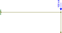
enter image description here

That's just a cantilever with a force applied at the free end. There's also a dangling vertical beam at the end (which is unsupported at the bottom).

Now, I don't need to know anything about the stiffness of each of those beam segments to determine how the load will be divided between them. We trivially know that dangling beam won't do anything, and all the load will be resisted by the cantilever. After all, that dangling beam might be infinitely stiff, but it's a dead end.

Now imagine you get the thinnest possible steel wire and use it to connect the bottom of the dangling beam to the support (with fixed connections, not pinned). Your structure diagram then becomes something like this:
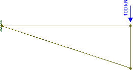
enter image description here

Now, given how weak that new diagonal "beam" is (just a tiny wire), we can probably approximate its stiffness as equal to zero (especially when compared to the stiffness of an actual steel beam). Which basically means we can pretend the diagonal doesn't exist. Therefore, the structure will actually behave exactly as it did in the original case: the entire load will be resisted by the horizontal beam.

So, that was easy enough.

But now imagine the diagonal and horizontal members were reversed: the diagonal is the steel beam and the horizontal is just a pitiful wire. In this case, we can obviously state that the load will travel down the vertical (previously dangling) beam and then up the diagonal towards the support, with the tiny wire not really doing much of anything.

But what if both the horizontal and diagonal beams are steel beams, and therefore both contribute to resisting the load? Well, then we can't trivially figure this out anymore.1

And that's why calculating the shear force and bending moment of statically indeterminate structures depends on the elements' stiffness: each element's stiffness defines how much load it must support. And the proportion of the load going to each element is directly proportional to its stiffness: the stiffer the beam (as compared to others sharing the load), the more load it must support.

As for your follow-up question, the answer is simply "no". Just think of the fundamental beam equation:

$$\dfrac{\partial^2}{\partial x^2}\left(EI\dfrac{\partial^2 w}{\partial x^2}\right) = q$$

This tells us that the first integral of the loading is the shear force, the second integral is the bending moment, the third integral is the angle of rotation times the stiffness, and the fourth integral is the deflection times the stiffness.

Obviously, the greater the load applied on a beam, the greater the shear force and bending moment will be and therefore, the greater the deflection. But if you change the beam's stiffness (and the applied loading remains the same), the bending moment will remain the same, but the deflection will change.

For example, if you double a beam's stiffness, how do you expect its deflection to behave?

The correct answer is that if you double the beam's stiffness, then the deflection will be halved. This is consistent with what I've said: the loading remained the same, therefore so did the shear force (first integral of loading) and bending moment (second integral of loading) diagrams. However, since the third and fourth integrals of loading are equal to the product of stiffness and rotation or deflection, the resulting rotation/deflection is halved if the stiffness is doubled (basically, $EIw = (2EI)(w/2)$).

If your idea were correct, then doubling the stiffness would lead to another answer: the bending moment diagram itself would change (say, decrease by half), and then the deflection due to that reduced moment would itself be reduced by half due to the stiffness coefficient when integrating from moment to rotation and deflection.


1 This is a bit off-topic, so putting this as a footnote. To actually calculate this case, you need to use compatibility equations which effectively guarantee that the diagonal's deflection at the free end is equal to the horizontal's deflection at its free end plus the vertical's compressive deflection. Basically equations which guarantee that everyone agrees where (and at which angle of rotation) the nodes end up in the structure's deflected shape.

$\endgroup$
2
$\begingroup$

In your example the change in the cross section of the beam doesn't have any effect on the end moment even if the beam is a hollow section such as a pipe as long as the ratio of length to depth is greater than 10.

When the beam is very deep and this ratio is less than 10, shear deformation and web warping effect could change the picture. We follow Euler- Bernoulli beam theory which is a great simplification of linear elasticity albeit a genius one. And that theory is very effective predictive of stresses when the beam is slender.

See a brief history of the theory here.

$\endgroup$

Your Answer

By clicking “Post Your Answer”, you agree to our terms of service and acknowledge you have read our privacy policy.

Not the answer you're looking for? Browse other questions tagged or ask your own question.