I am trying to find out how much lateral thrust an arch produces when applying a load evenly distributed across its span. There are a lot of 'complex' models around and full analysis done case by case that are quite time consuming to replicate. Instead, I would like to be able to quickly determine (perhaps with a simplified formula) what % percentage of the vertical load on top of the arch is distributed laterally, depending for example on the height / span ratio. Is it possible to come up with such an estimation?
2 Answers
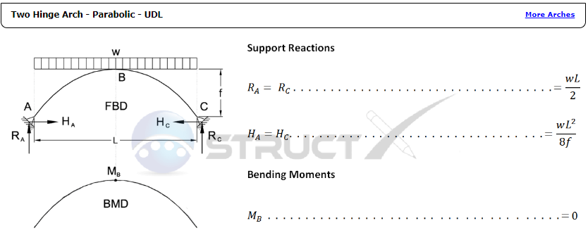
For a two-hinged parabolic arc under Uniformly Distributed load ignoring the arc's self-weight the vertical and horizontal reactions are easy and straightforward. source
$$R_r= R_l =\frac{ WL}{2}$$
$$H_r= H_l =\frac{WL^2}{8C}$$
Notation FBD = free body diagram BMD = bending moment diagram
A= left support
C = right support
f = height of arch from supports, in or mm
H = horizontal reaction load at bearing point, lbf or N = L = span length under consideration, in or mm
M = maximum bending moment, lbf.in or Nmm
R = vertical reaction load at bearing point, lbf or N
w = load per unit length, lbf/in or N/mm
-
$\begingroup$ Thanks! This is very helpful, however it only covers a parabolic arch which as far as I know, produce significant horizontal thrust. What about rounded arches or more generally lancet arches? The resource you linked has a section for "any shape" however the results seem identical to parabolic arches so I am not sure if they are valid for round/lancet arches $\endgroup$ Commented Nov 1, 2023 at 17:09
-
$\begingroup$ Still, it is true. If we ignore the self-weight (no catenary) and the load is horizontal, any shape—even a combination of different sections with different "I"s or a mix of straight segments roughly looking like an arch—will have the same support vertical and lateral reactions, provided they do not fail and become a mechanism. Create multiple shapes' free-body diagrams to verify the results for yourself. While the support reactions only follow the proportion of the rectangle that frames the arch, the member stresses will differ. $\endgroup$– kamranCommented Nov 1, 2023 at 18:48
-
$\begingroup$ What doesn't convince me is that from WL^2 / 8f, which we can re-arrange as M x L / 8f, where M is the total load over the arch span, we can then say that L/8f is the fraction of total load that is transferred as lateral thrust in one support. If L > 8f (i.e. 1 meter span and 10cm height) according to that formula we get more lateral thrust than actual load on top of the arch, which is impossible $\endgroup$ Commented Nov 1, 2023 at 20:47
-
$\begingroup$ Let's see it this way. if you have an arch or say a triangular truss and for the sake of simplicity total load M is concentrated on the triangle's top corner if the angle of the side members is a. For a>45 we get the lateral reaction H< M/2 but for a<45 H>M/2 it can rapidly approach infinity as a becomes smaller. for a flat aspect ratio arch the lateral reaction can be much greater than the M. $\endgroup$– kamranCommented Nov 2, 2023 at 0:11
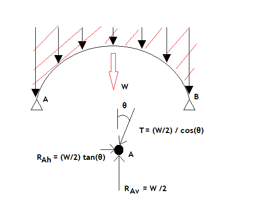
A "quick and dirty" way to get horizontal loading at an arch support is to use an approach similar to the joint method with trusses.
Assuming the total weight W carried by the arch is evenly supported across the entire arch, we can also assume each arch support vertically carries W/2. This is the vertical reaction, Rv. Then just take W/2 and multiply by tan(θ), where θ is the angle the arch makes with vertical at the support location.
So for the horizontal reaction Rh we have:
Rh = (W/2) x tan(θ)
And for the thrust in the arch structure, T, we have:
T = (W/2) / cos(θ)
As far as restrictions to this estimate: for a round arch, almost all of the horizontal reaction is going to be due to thrust. So in practice, this is a good estimate.
But the reality is that every arch is also going to carry shear forces, because no arch on Earth can actually be perfectly loaded so that no shear loads are induced. So to perfectly account for all of the horizontal reaction load, you'd need to also compute the shear, and resolve the shear into vertical and horizontal components using the joint method, too. But as already stated, for round arches, this shear is going to be negligible.
-
$\begingroup$ What are the limits of validity of this approximation? They seem fairly restrictive. For an arch whose profile is obtained by combining section of a circle (round/lancet arches) don't we get θ = 0 (or anyway a very small angle) which implies there is no horizontal thrust? $\endgroup$ Commented Nov 1, 2023 at 17:15
-
$\begingroup$ @Redirectk If the angle theta is zero (or in other words: the angle the arch legs make with the ground/invert/bottom is 90 degrees), yes, the horizontal reaction is zero, unless there's shear in the arch wall at that location instead of just thrust. Shear in this theta=0 case occurs when the arch isn't perfectly evenly loaded, like when it is buried in soil, or subjected to gravity (ie, the load direction with respect to the arch is changing with the arch angle as you go around). So in other words: all arches on Earth. ;) But the difference usually isn't that large. $\endgroup$– RickCommented Nov 2, 2023 at 15:44
-
$\begingroup$ @Redirectk for example: in the AASHTO highway design code, buried flexible (such as corrugated metal) arches with theta=0 are allowed to be assumed to have no horizontal reaction for empirical design purposes, even though in reality they do. But a box shape- with straight vertical legs- would not. $\endgroup$– RickCommented Nov 2, 2023 at 15:50

