I'm currently working on problems for my mechanics of material course, and I just learned how to calculate the shear stress on a bolt holding stacked plates. That whether it be a single or double shear, I have to account for every shear plane. However, what happens for the bearing stress? I know that it depends on the area of contact, which is diameter * thickness of the plate. If there were three plates (double shear) and I looked at only the portion of the bolt in each plate, would the bearing stress not differ? Do I have to look at the entire bolt at once to calculate the bearing stress?
3 Answers
I think answer to the question would the bearing stress differ is ==>
YES!
bearing stress would vary along the bolt in different sections in plates...
and you cannot look at the entire bolt at once to calculate the bearing stress
here is a pictorial explanation why do we need to consider it in different sections & how to calculate bearing stresses (if you want to).
let us assume that we have a 3 plate arrangement like shown in pic.

where this blue thing on the right is called CLEVIS and on the LHS we have a plate.
Looking at the cross sectional view let us say:
that
This connection consists of a flat bar A (which i will refer here as just plate), a clevis C, and a bolt B that passes through holes in the plate and clevis. Under the action of the tensile loads P, the plate and clevis will press against the bolt in bearing, and contact stresses, called bearing stresses, will be developed.
Bearing stresses being contact stresses depend upon the contact between two surfaces so the answer to * Do I have to look at the entire bolt at once to calculate the bearing stress * is answered here and the answer is NO
you have to look at each contact area not just because you want to calculate but more because looking at the entire bolt at once to calculate the bearing stress is CONCEPTUALLY WRONG!!!
& NOW, assume that clevis has upper and lower plate of different thickness... even if it doesn't look like...
but let's just say it for a moment.
these two plates of CLEVIS (upper and lower) are under forces say: $P_1$ and $P_3$ (respectively).
and using equations of static equilibrium: $P_1$ + $P_3$ = $P$
The Bearing stresses exerted by the clevis against the bolt appear on the left-hand side of the free-body diagram (see 1 and 3) .
&
The Bearing stresses from the plate appear on the right-hand side (see 2).
Here, we make an assumption i.e.:
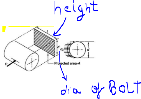
Since, The actual distribution of the bearing stresses is difficult to determine, so we customarily assume that the stresses are uniformly distributed.
Based upon the assumption of uniform distribution, we can calculate an average bearing stress $\sigma_{b}$ by dividing the total bearing force $F_b$ by the bearing area $A_b$ , since stress is Force divided by acting area.
The projected area $A_b$ on which they act is a rectangle having a height equal to the thickness of chosen plate (upper or lower) of the clevis and a width equal to the diameter of the bolt.
SO,following would be the EXPRESSIONS for bearing stresses at different contacts:
$plate_1$ (of clevis) \begin{align} \begin{pmatrix} \sigma_1 = \dfrac{P_1}{d * t_1} \end{pmatrix} \end{align}
$plate A$ \begin{align} \begin{pmatrix} \sigma_2 = \dfrac{P}{d * t_2} \end{pmatrix} \end{align}
$plate_3$ (of clevis) \begin{align} \begin{pmatrix} \sigma_3 = \dfrac{P_3}{d * t_3} \end{pmatrix} \end{align}
and until and unless $t_1$ == $t_3$ bearing stresses would differ
Bolt shear is a limit state for the bolt, whereas bearing stress is more a limit state for the connected plates. Therefore, it makes sense to evaluate bearing stress on a plate-by-plate basis. When two or more plates are sharing the load, you can consider the total thickness in each loaded direction versus the total applied load.
I suppose that in principle, when two or more plates are sharing the load you could split the load between the plates based on relative bearing area and evaluate adequacy on a plate-by-plate basis. However, since the loaded 'width' is the same for all plates (i.e. the bolt diameter) this approach would give the same result.
A little qualitative thought experiment:
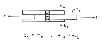
- There are two shear planes and three bearing 'areas'
- The stress on the two shear planes is equal
- The $Plate_1$ load + $Plate_2$ load = $Plate_3$ load
- Load in $Plate_1$ > load in $Plate_2$ (because $t_1$ > $t_2$)
Bearing stress at $Plate_1$ = bearing stress at $Plate_2$ = $\frac{P}{bolt diameter(t1 + t2)}$
If ($t_1$ + $t_2$) = $t_3$ then the bearing stress is uniform along the bolt length, otherwise it will vary
For a single bolt clamping one middle plate between two side plates (assume both of the same thickness but not necessarily the same as the middle plate), the joint can fail by:
- shearing of the bolt, but it is double shear, so double the bolt area.
- bearing (i.e crushing) failure of the hole in the middle plate alone, so bolt diameter x plate thickness.
- bearing failure of the side plates but both have to fail for the joint to fail, so double the bearing area of one hole.
The essential question you should ask is 'what area of material must fail for the whole joint to fail?'
You must also check for the possibility of tensile failure of the plates: if the holes are large compared to the plate width, this might be the failure mode.


