0
$\begingroup$

I'm making pocket holes to connect wood together with a jig, the Kreg 720. The 720 works by moving at an angle (which I'm trying to measure) to ensure the hole is drilled higher on thicker pieces.

The jig makes a hole like this at a 15 degree angle. enter image description here
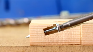
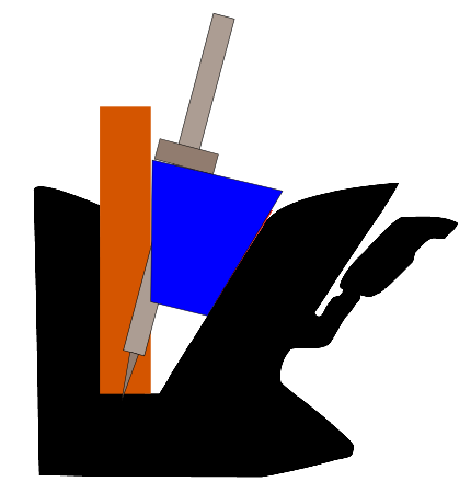
The 720 works like this:

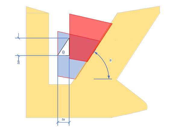
enter image description here

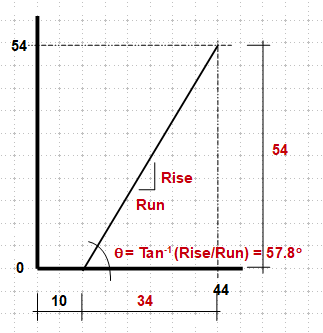
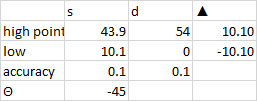
I'm trying to calculate the length of the drill bit which I can set with a stop. The 720 has stops included for common wood, but I like to be exact and I need to understand the geometry of how the 720 works. I zeroed out an angle meter and found that the case is 57 degrees, but I took some measurements at the top and bottom and through taking the tangent, figured out that the sliding block moves closer to 58 degrees.

s d
high point (mm) 43.9 54
low 10.1 0
accuracy 0.1 0.1
$\Delta$ 33.8 54
$\theta$ 57.95648

But! I wanted to make sure that the drilling jig block moved at 57 degrees, so I used my caliper to measure the board thickness block at the bottom and the top. That gave me these measurements.

enter image description here

Per this geometry: enter image description here

From this I'm trying to find $D$ the length of the shaft of the pilot screw given $t_{\text{min}}$, the minimum thickness, $t_b$ the thickness of the board for pocket holes, $t_T$ the thickness of the board you are screwing into, $\theta$, the angle of the jig, and $s$, the length of the shaft of the screw.

$\endgroup$
9
  • $\begingroup$ Can you show the "d" & "s" on your sketch? $\endgroup$
    – r13
    Commented Jan 22, 2022 at 18:11
  • $\begingroup$ On the sketch above d is the vertical dimension, I just show $\Delta$ d. $s$ is the horizonal distance, I show $\Delta$ s. I'm adding a picture to show exactly what I measured. $\endgroup$
    – bonhoffer
    Commented Jan 22, 2022 at 18:28
  • $\begingroup$ In the third image (the one that you have noted $\delta d$, and $\delta s$, you can see that they are different. It is unclear --to me at least-- how exactly you obtained the two measurements you have on the table just above (measuring 10.1 for each one). It would be helpful to show how you used the calipers to do the mearurements. $\endgroup$
    – NMech
    Commented Jan 22, 2022 at 19:15
  • $\begingroup$ in that image, you have $d$ and $s$ at the top. at the bottom $d = 0$, $s = 10.1 \text{mm}$ does that clear it up? I added an image of what I measured at the bottom. $\endgroup$
    – bonhoffer
    Commented Jan 22, 2022 at 19:31
  • $\begingroup$ You do have my thinking, that I need to be able to compare those two images and show that the rise is equal to the run. Otherwise, its 57-ish not 45 :( $\endgroup$
    – bonhoffer
    Commented Jan 22, 2022 at 19:36

3 Answers 3

1
$\begingroup$

I think you're over-complicating this. The angle of the jig and wedge is twice the angle of the screw. It's designed to bring the tip of the bit out in the centre of the edge of the piece being drilled and automatically compensates for the timber thickness.

enter image description here

Figure 1. Set-up procedure.

  1. Insert a piece of timber into the jig and clamp it so that one of the holes is not blocked.
  2. Drop the drill bit in so that the point touches the bottom.
  3. Lock the depth stop ring.

That should result in the tip just breaking through the edge right on centre. This will give you good pull on the centre-line of the timber giving best chance of a 90° joint. You should also have just the right length of screw shank in the hole and minimum risk of tear-out.

If you want the tip to break through further then slip an appropriate hex/Allen key under the stop ring under the stop ring before tightening it up.

Further notes from the comments:

If the black slope is 58° from horizontal then it is 32° off vertical. My blue block would form a truncated wedge with an angle of 32° at the bottom. I would expect the drill bit and screw to be at 16° from vertical. That's pretty close to your 15°. The drill bit angle has to be half the wedge angle if it is to intersect the base at half the width of the board.

$\endgroup$
3
  • $\begingroup$ That is super helpful and gives me better insight into how this is set up. I am confused on what angle you are describing as the "angle of the jig and wedge" that is twice the angle of the screw. The screw angle is exactly 15 degrees. I'm pretty sure the blue block translates around 58 degrees. $\endgroup$
    – bonhoffer
    Commented Jan 22, 2022 at 21:31
  • 1
    $\begingroup$ If the black slope is 58° from horizontal then it is 32° off vertical. My blue block would form a truncated wedge with an angle of 32° at the bottom. I would expect the drill bit and screw to be at 16° from vertical. That's pretty close to your 15°. The drill bit angle has to be half the wedge angle if it is to intersect the base at half the width of the board. $\endgroup$
    – Transistor
    Commented Jan 22, 2022 at 22:25
  • $\begingroup$ a mech-e friend has said this is just an application of Mohr circles. I drew out the geometry and proved $\phi = 2* \theta$, but I think I'm missing an intuitive understanding. Can you shed any light on why this works? $\endgroup$
    – bonhoffer
    Commented Jan 27, 2022 at 12:06
1
$\begingroup$

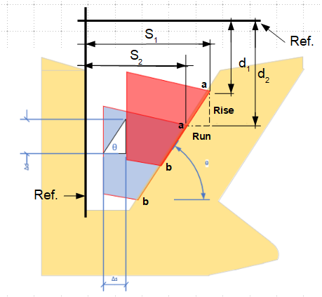
This is what your measurements tell me:

enter image description here

This is the suggested measurement you shall take if you are interested in the incline of the cutting plane. (Note, "a" is a fixed point on the moving drill bit)

enter image description here

$\endgroup$
0
$\begingroup$

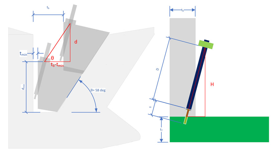
I worked on this a bit, and set up the following two scenarios: (1) the translation of the sliding block along the 58 degree line and (2) the pilot hole and screw in the boards.

enter image description here

From this I can calculate get an equation for $D$ from the scenario on the right.

$$D = \frac{H}{\cos(15 \deg)} - \frac{s}{2}$$

On the left, I can get $d$ from the red triangle with $\theta = 58$

$$d = \tan(\theta) \, \left( t_b -t_{min} \right) \text{ where } \theta = 58 \deg $$

Putting these together from $H=d_{\text{min}} + d$ we have:

$$ D = \frac{ d_{\text{min}} + \tan(58 \deg) \, \left( t_b -t_{min} \right) }{\cos(15 \deg)} - \frac{s}{2} $$

$\endgroup$

Your Answer

By clicking “Post Your Answer”, you agree to our terms of service and acknowledge you have read our privacy policy.

Not the answer you're looking for? Browse other questions tagged or ask your own question.