0
$\begingroup$

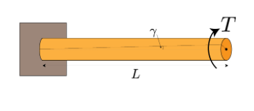
Consider a shaft which is fixed at one of the ends and is acted upon by a torque at the free end as shown.
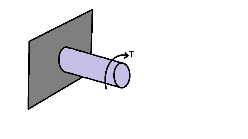
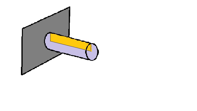
enter image description here We take a plane inside the shaft as shown in the figure before the torque is applied. I'm interested in knowing how the plane will look after the torque has been applied.

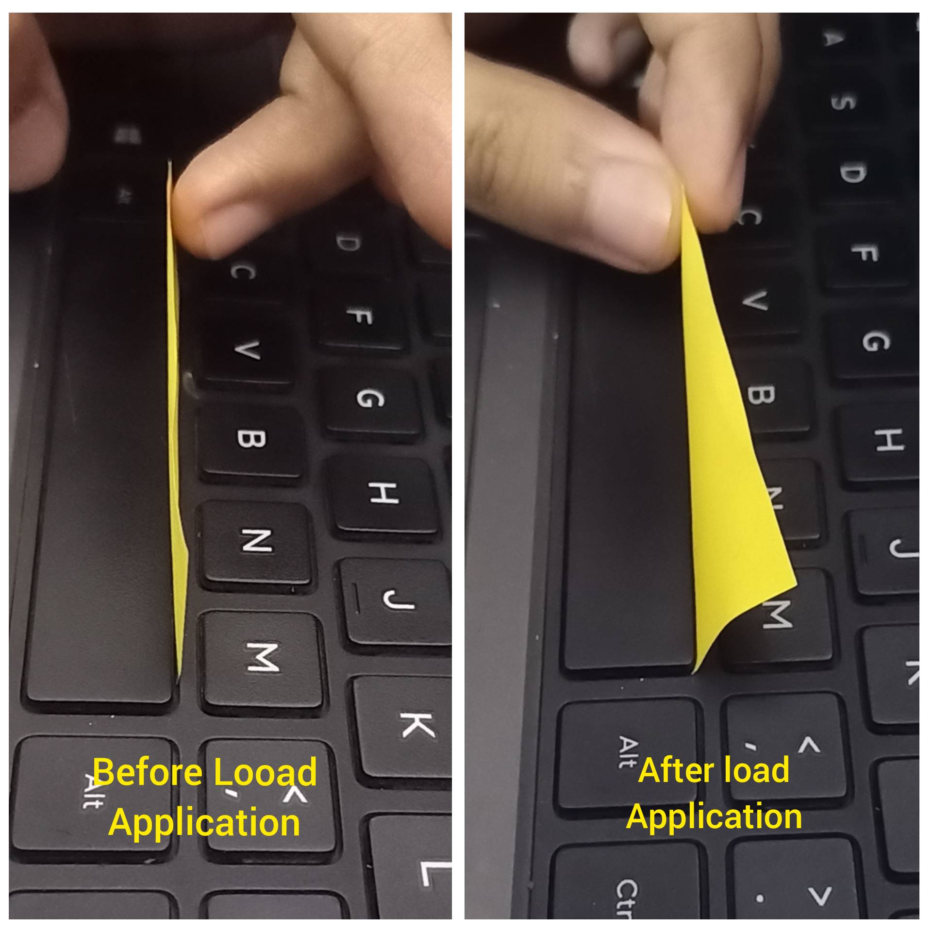
enter image description here

My intuition tells me that the plane will be bent (for the lack of a better word) after the loading as shown below. (
enter image description here However if that is the case, the radial lines will curve at the end of loading and one of the major assumptions that the book I'm referring to for studying torsion in circular shafts, is that the radial lines must remain straight at all times.

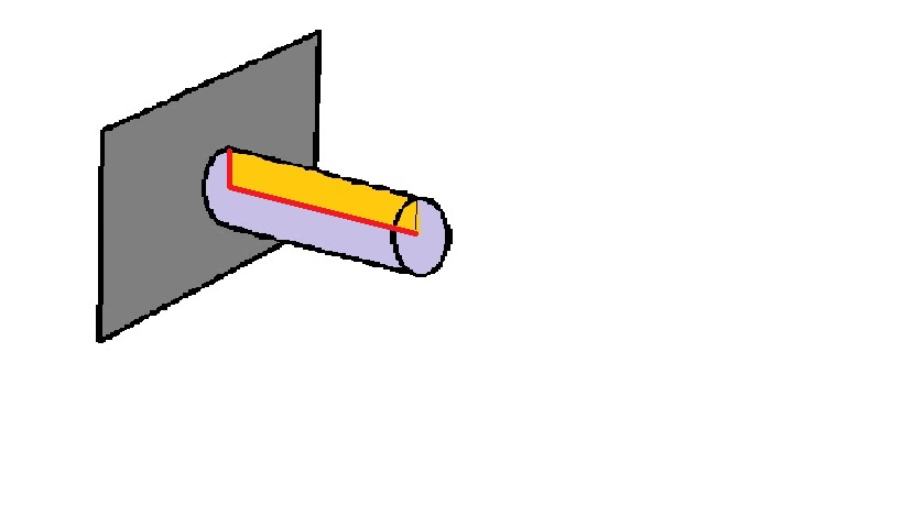
Conversely, if the radial lines are to remain straight at all times, that would mean the plane after the loading doesn't bend and remains flat. However, is this possible physically, provided that the two edges (shown in red below) are fixed.
enter image description here

$\endgroup$
2
  • $\begingroup$ what do you mean by radial lines? $\endgroup$
    – NMech
    Commented Dec 15, 2021 at 10:42
  • $\begingroup$ Like the radius. In the third image the radius is straight before but has curved after the loading $\endgroup$ Commented Dec 15, 2021 at 10:45

2 Answers 2

2
$\begingroup$

Your intuition that the plane twists is correct in the case of the circular cross-sections (at least); although the example in the image is not representative.

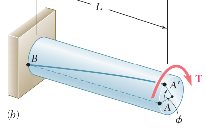
The total cross-section rotates uniformly. I.e. every point on the cross-section rotates by an angle $\theta$. So you end up with a cross-section like:

enter image description here

Figure: torsion angle (source: Beer mechanics of materials)

The total rotation angle (in the elastic/linear range) at each point is given by:

$$\theta = \frac{M \cdot L}{G\cdot J}$$

where:

  • M is the torque
  • L is the distance
  • G is shear modulus
  • J is the polar moment of inertia.

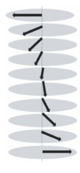
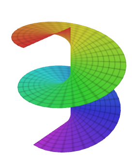
So each crosssection rotates the same -- although the center point does not seem to move at all. So the surface that is swept is a twisted plane. More like a helical plane

enter image description here enter image description here
$\endgroup$
8
  • $\begingroup$ Nice illustrations. If the plane turns to a helical plane after loading, then won't the radial lines, become curve? In that case the assumption that the radius must remain straight would be contradicted. The first time I studied the theory of torsion in circular shafts, I interpreted the twisting of the plane as a being a helix, as you told. I was revisiting the concepts today, and the assumption - Radius remains straight at all times, caught my eye, which seems to contradict the helical plane argument. $\endgroup$ Commented Dec 15, 2021 at 11:39
  • $\begingroup$ That's why I added the illustration. Particularly the left one on the last line. You see that the radial lines are straight, however what they form is not a planar surface/plane. Insted you have this helicoid. In the helix, the radial lines are straight, check the right image on the last line $\endgroup$
    – NMech
    Commented Dec 15, 2021 at 11:42
  • $\begingroup$ Ohh. So it is possible to have a helical plane with the radial lines being straight. So for a shaft fixed at one end this - ( drive.google.com/file/d/1giAHe85d6DDrG0HZQwX8V_RqkJTQ6ebq/… )will be the situation right? with the radial lines (shown in green) being straight and the plane being flat even after torsion. $\endgroup$ Commented Dec 15, 2021 at 12:43
  • 1
    $\begingroup$ Yes exactly. The main difference with the post it is that is basically a cantilever beam in bending. However in the circular cross-section the adjacent component offer support and rotate together. $\endgroup$
    – NMech
    Commented Dec 15, 2021 at 12:45
  • 1
    $\begingroup$ And another thing, it is very important how the torque is applied on the cross-section. If you clamp on the perimeter then you might see some bending of the radial lines. Normally, though (or if the radius is relatively small) the assumption is that the torque is spread across the entire cross-section. $\endgroup$
    – NMech
    Commented Dec 15, 2021 at 13:15
2
$\begingroup$

One easy way of imagining the deformation of the plane you show in your sketch is to cut the shaft into infinitesimally thin disks with thickness, dL, and imagine these disks look like a clock with only an hour hand at 12oc. Then rotate each disk by the amount of.

$$ \theta = \frac{32dL T}{ (\pi G D^4)}$$

  • T= torque
  • $\theta$ = angle of rotation
  • D = dimeter of shaft
  • G = shear modulus of regidity
  • π D^4 / 32 = J, polar moment of inertia of shaft

The hour hand now traces a curve and the plane in your sketch is now the plane generated by this curve and the central axis of the shaft.

The Important thing is $the\ thin\ disks $ remain $plane $ after deformation according to $St \ Venant.$

This is true only for small-angle deformations though.

.

torque

$\endgroup$

Your Answer

By clicking “Post Your Answer”, you agree to our terms of service and acknowledge you have read our privacy policy.

Not the answer you're looking for? Browse other questions tagged or ask your own question.