MOTOR REQUIREMENTS
Start-up
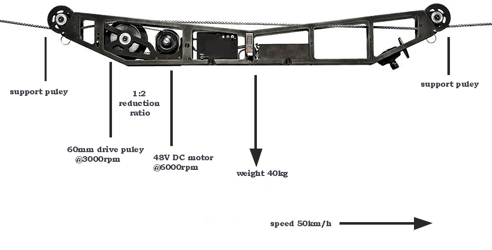
The force to overcome the friction equals $$ F_s^{max} = \mu_s m g=0.7 \cdot 40\text{ kg} \cdot 9.8\text{ m/s}^2=274.4\text{ N}$$
Required torque of the output pulley to start up equals $$ \tau_{pulley} = F_s^{max} \cdot \dfrac{d_{pulley}}{2} = 274.4\text{ N} \cdot 30\text{ mm} = 8.2\text{ Nm} $$
Reduction ratio is 1:2, assuming a efficiency of 90% means the motor should provide a torque that equals
$$ \tau_{motor} = \tau_{pulley} \frac{1}{i} \frac{1}{\eta} = 8.2\text{ Nm} \cdot \dfrac{1}{2} \cdot \dfrac{1}{0.9}= 4.6\text{ Nm}$$
6000 oz-in stall torque (which is the torque at 0 rad/sec) equals 42.3 Nm which is more than enough to overcome the required 4.6 Nm.
Acceleration
The force to accelerate the load equals $$ F_{acc} = ma = 40\text{ kg} \cdot \dfrac{ 50\text{ km/h}}{10\text{ sec}} = 55.6\text{ N}$$
Note that the friction still needs to be overcome, the required force equals $$ F_{total}=274.4\text{ N} +55.6\text{ N}= 330\text{ N}$$
Applying the same equations leads to
$$ \tau_{motor} = 330\text{ N} \cdot 30\text{ mm} \dfrac{1}{2} \dfrac{1}{0.9} = 5.5\text{ Nm}$$
In motion
When the rig is at 50 km/h, the friction force still needs to be overcome.
The required angular velocity of the motor (using the reduction ratio) equals
$$ \omega_{motor} = \frac{v_{rig}}{d_{pulley}/2} \cdot i= \frac{13.9\text{ m/s}}{30 \text{ mm}} \cdot 2 = 926\text{ rad/s}=8842 \text{ rpm}$$
This is exceeding the motor speed
When changing the reduction/gear ratio to 1:1, the motor torque to overcome friction becomes $$ \tau_{motor} = 9.1\text{ Nm} $$ and the torque to accelerate $$ \tau_{motor} = 11\text{ Nm} $$.
The required velocity in motion becomes $$ \omega_{motor} = 4421 \text{ rpm}$$
NOTE
I used a load of 40 kg, but such a big motor has quite some weight as well. This should be taken into account and recalculation needs to be done.
GRAPH WITH MOTOR CURVES
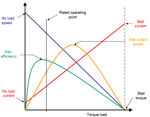
Some motor manufacturers provide curves with speed, power and efficiency with respect to torque.

Mechanical working points
In this graph the blue curve is relevant for the (mechanical) equations done above. This line represents what speed the motor can achieve for given torque at the rated voltage of 48V.
- At start up, the motor speed is 0 rpm and the required motor torque is 9.1 Nm, so we can draw a point at (9.1 Nm, 0 rpm).
- In motion, the motor speed is 4421 rpm and the required motor torque is 9.1 Nm, so we can draw a point at (9.1 Nm, 4421 rpm).
- During acceleration the required motor torque is 11 Nm and the motor speed increases from 0 rpm to 4421 rpm, so we all these points (forming a line) from (11 Nm, 0 rpm) to (11 Nm, 4421 rpm).
All points are drawn left and below the blue line, which means the motor is able to start up, accelerate and keep the rig in motion.
It seems dull to add the start up and in-motion points, as the acceleration points cover these already. However, some systems need to overcome more start-up forces and/or apply a different acceleration profile.
For dc motors applies:
- the motor torque is proportional to the motor current
- the motor speed is proportional to the motor voltage
Reducing the applied motor voltage shifts the blue line. Controlling a dc motor is "shifting the blue line downwards/to the left" by lowering the motor voltage till it intersects with the points drawn above. (It is possible to overdrive the motor with a higher voltage than 48V, but I wouldn't recommend it. Moreover, as your battery voltage is 48V, it would require addition means)
Note that the battery voltage may lower during use, so, changing the reduction/gear ratio to 4:3, gives more headroom.
Motor current
The red curve in the graph is the current for given torque.
The current ratings for the motor have been given as:
- no load current = 4.5 A (at zero torque = 0 Nm)
- stall current = 650 A (at stall torque = 42.3 Nm)
So, the relation between torque and current is
$$ I_{motor} = \tau_{motor} \frac{650\text{ A}-4.5\text{ A}}{42.3\text{ Nm}} + 4.5A $$
(Using the reduction/gear ratio to 1:1) the required torque to accelerate eqauls 11 Nm, so the required current becomes 172 A.
To keep the wig in motion, a torque of 11 Nm is required, requiring a current of 143 A.
**This exceeds the current ratings of the motor controller (and battery) **
Using the former reduction ratio to 2:1 requires 4.6 Nm to keep the wig in motion, so a contineous current of 74 A. This almost satisfies the current rating of the motor controller, but the required speed cannot be achieved as shown above.
SUMMARY
- The motor is able to comply the requirements, especially using a gear ration of about 4:3.
- The motor controller fails to comply as it either limits the maximum torque or the maximum speed.
ADVISE
Note that the friction force is 5 times as big as the acceleration force. So, down-scaling the requirement for acceleration has hardly no use.
The friction force is proportional to the payload as well as the friction coefficent. Improving the latter may yield interesting results.

