1
$\begingroup$

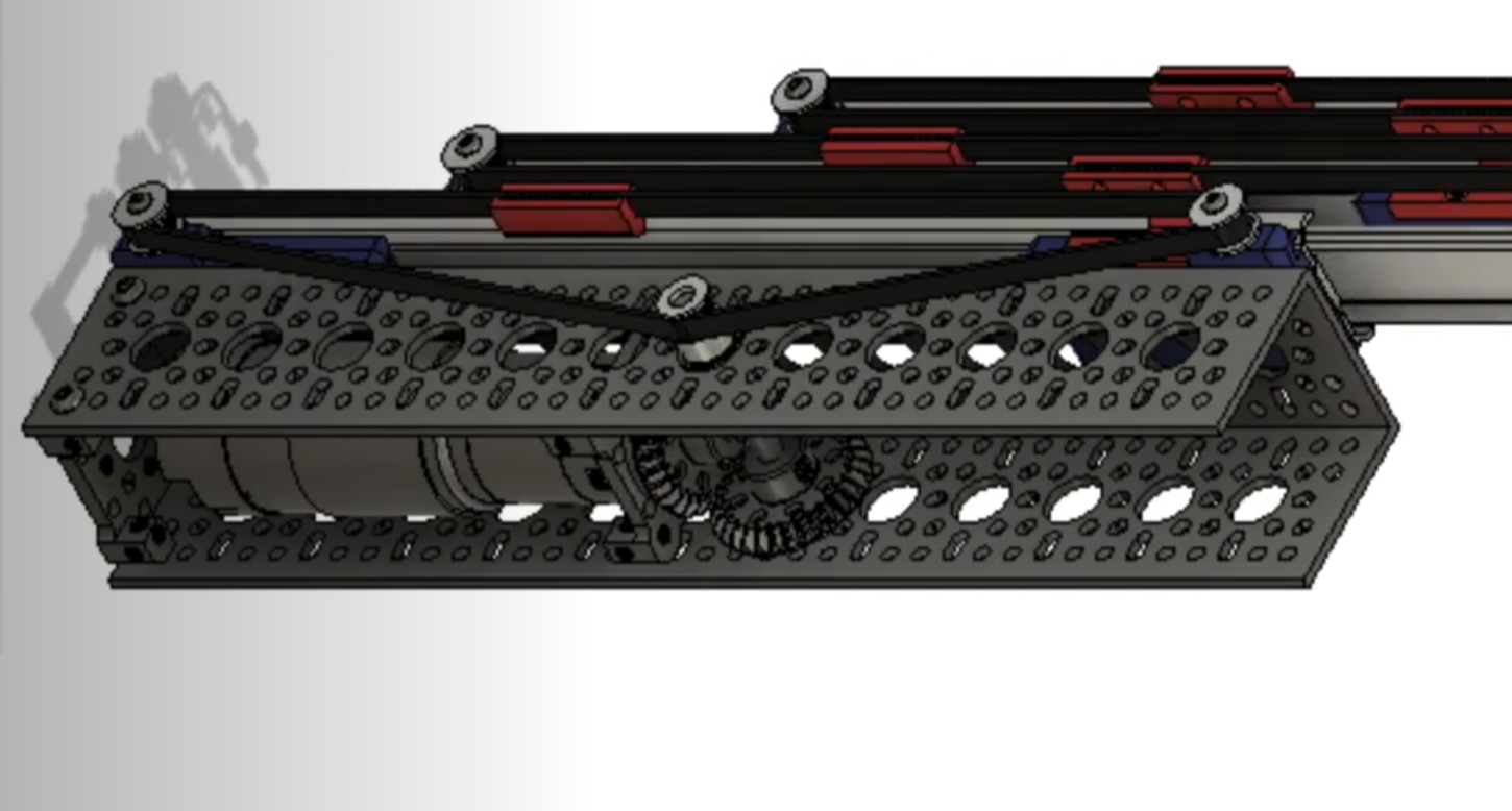
I am working on a belt-driven linear motion mechanism using drawer slides (I've attached a small video that shows the Mechanism for my First Tech Challenge Team.

enter image description here

I was now wondering how much torque the motor would need given the constraints I defined (in the PDF linked below). I've already attempted to calculate it using my basic 1st semester AP Physics knowledge and Google, however, I believe that the calculations I did would be for a lever/arm mechanism and not for this. I'm not taking into account friction or air resistance in this calculation to try to limit the complexity.

Constraints and Calculations PDF

$\endgroup$
7
  • 1
    $\begingroup$ Friction will be the significant: bearings etc so why ignore that? $\endgroup$
    – Solar Mike
    Commented Dec 10, 2021 at 6:24
  • $\begingroup$ So disconnect the motor, fit a lever of a known length and pull using a spring balance to get some ball-park values. $\endgroup$
    – Solar Mike
    Commented Dec 10, 2021 at 8:49
  • $\begingroup$ Cool mechanism concept. Besides the other stuff mentioned, I'd take a closer look at the contact between the belt and the drive pulley/sprocket. When the belt wraps around approximately 180 deg, it's not problem, here it wraps around maybe 30 deg, which might limit the torque it's capable of transmitting before slipping -- because of the angle on the trapezoidal profile of the teeth. Looking at it another way, this could require the tension to be set to a higher than typical value, further increasing friction... speaking of which, what controls/adjusts the tension? $\endgroup$
    – Pete W
    Commented Dec 10, 2021 at 14:40
  • 1
    $\begingroup$ @PeteW I didn't even think of that, I'm gonna go back and redesign it to increase that wrap around to hopefully 90+ degrees to increase the torque limit, considering the fact that I am using 2mm pitch GT2 belt. To control tension I was going to place an Idler on the channel somewhere which I could move to adjust the tension or readjust the clamps to increase tension. $\endgroup$
    – Neil
    Commented Dec 10, 2021 at 15:47
  • $\begingroup$ Or you could put two idlers and wrap the belt more around the drive pulley… $\endgroup$
    – Solar Mike
    Commented Dec 10, 2021 at 16:04

3 Answers 3

2
$\begingroup$

Regarding the calculations that you've made I have the following comments:

  • Acceleration/Deceleration you are calculating the necessary acceleration as a constant acceleration, while it should be increasing for the first half and decreasing for the second half.

Otherwise the drawer will have a maximum velocity at the end and it will abruptly stop with a bang everytime it opens or closes. (A more preferable solution IMHO would be to accelerate for a quarter of the length, then the velocity to remain constant for half the length and finally decelerate for the final length).

For the simple case of accelerating for half the distance and then decelerating for the remaining:

$$a = \frac{2\cdot \left(D_{max} \over 2\right)}{\left(T_L \over 2\right)^2} = \frac{4\cdot D_{max}}{T_L ^2} $$

So the acceleration of the load is double.

  • Acceleration of the masses:

Apart from the load that you need to accelerate, you also need to consider the force required to raise the individual "drawers". There is no indication here for that value.

Also keep in mind that the middle drawer requires half the acceleration to the one that is pushing.

Of course this can be neglected, if the masses involved are less than 10 times the Load.

  • Rotational Acceleration of the rotating shafts:

Depending on the acceleration (the time $T_L=0.75 s$ seems to me quite high), you might need to also consider the torque required to accelerate/decelerate the rotating shaft.

Again for a first analysis that can be neglected.

  • Tension of the belts and Friction:

This is probably the most important but the most difficult to calculate in advance. The friction can be vastly different (from insignificant to dominant) depending of the:

  • assembly construction
  • the bearing used (and their quality)
  • The tension on the belt pulley
  • cleanliness
  • .... (and a host of other factors)

. If you have no other data, my approach would be to at least double the total torque calculated from the other sources.

$\endgroup$
1
  • $\begingroup$ I do plan to double the torque calculated, I think I forgot to clarify this in the question but, the main thing I think I am doing wrong is that the acceleration I calculated is for the drawer slides and the radius is for the pulley? Could you clarify this for me $\endgroup$
    – Neil
    Commented Dec 10, 2021 at 19:09
0
$\begingroup$

To reduce torque you need to prolong the time your system accelerates. Almost all the 0.75s

You can design the system to accelerate through say *0.95L * and then cut off the power and let a small rubber damper break the move to stop.

Your calculations seem to be okay, If the drawer slides horizontally as per your figure we don't need the gravity part (g*L). We would add a bit of extra torque to make up for tear and wear.

$\endgroup$
0
$\begingroup$

If I am not mistaken, you have one fixed base part, to which the torque creating motor is attached, and 3 moving parts of the mechanism (the three drawer slides). This mechanism has one degree of freedom. You seem to be ignoring the masses of the three slides, so I would ignore them too. It is not clear to me whether you are lifting the load vertically with this mechanism or horizontally (i.e. presence of gravity or no presence of gravity).

I tried to apply Lagrangian formalism to this model, and in particular D'Alembert's principle.

Observe that by construction of the mechanism, the belt on the fixed base part is the one driven by the motor, so when in motion, we can introduce displacement $x$ of the said belt. That displacement displaces the first slide at distance $x$ from its initial position, the second slide is displaced at distance $2x$ from its initial position, and the third slide is displaced at distance $3x$ from its initial position. Since the load is on the third slide, the displacement of the load is $x_{load} = 3x$.

It seems to me that, since the slides are massless, the Lagrangian of this system should be $$L \, =\, \frac{m}{2} \left(\frac{dx_{load}}{dt}\right)^2 \, -\, m\, g\, x_{load}$$ (simply the kinetic minus the potential energy of the load, as the load is the only object with mass). Now, using the displacement $x$ as a generalized coordinate, the Lagrangian becomes $$L \, =\, \frac{m}{2} \left(3\, \frac{dx}{dt}\right)^2 \, -\, m\, g\, \big(3\,x\big) \, =\, \frac{9\,m}{2} \left( \frac{dx}{dt}\right)^2 \, -\,3\, m\, g\, x$$

Since the torque $\tau$ in question generates a linear force $F$ along the belt on the fixed base part, the said force causes virtual displacement $\delta x$ of the belt. D'Alembert's principle then implies $$\left(\frac{\delta}{\delta x} L\right) \delta x \,= \, F\delta x$$ which holds if and only if $$\frac{\delta}{\delta x} L \,= \, F$$ From Lagrangian mechanics, $$\frac{\delta}{\delta x} L \, =\, \frac{d}{dt}\frac{\partial L}{\partial \dot{x}} \, -\, \frac{\partial L}{\partial {x}} \, = \, F$$ ($\dot{x} = \frac{dx}{dt}$) For this model, the equation of motion is therefore $$ {9\,m} \frac{d^2x}{dt^2}\, + \,3\, m\, g \, =\, F$$ Now, the linear force $F$ is related to the torque by the relation $$\tau \, =\, r \, F$$ Thus, finally we get $$ {9\,m} \frac{d^2x}{dt^2}\, + \,3\, m\, g \, =\, \frac{\tau}{r}$$ or alternatively $$ \frac{d^2x}{dt^2}\, \, =\, \frac{\tau}{9\,m\,r} \, -\, \,\frac{g}{3}$$ Assuming that the torque $\tau$ is constant for half the time of the full extension of the mechanism, we can integrate the latter equation twice, obtaining the law of motion $$x \, =\, \frac{t^2}{2}\left(\frac{\tau}{9\,m\,r} \, -\, \,\frac{g}{3}\right)$$ Hence, the actual law of motion of the load is $$x_{load} \, =\, \frac{t^2}{2}\left(\frac{\tau}{3\,m\,r} \, -\, \,{g}\right)$$ If the full extension of the mechanism is $x_{load} \,=\, D$ and the time to achieve it is $T$, then one simple scenario is uniformly accelerating, applying constant toque $\tau$ in one direction , for half of the total time $T$, then uniformly decelerating, applying constant toque $\tau$ in the other direction, for the remaining half of the total time $T$. This means that we want when $t = \frac{T}{2}$ the displacement to be $x_{load} = \frac{D}{2}$. So plug it $$\frac{D}{2} \, =\, \frac{(T/2)^2}{2}\left(\frac{\tau}{3\,m\,r} \, -\, \,{g}\right)$$ $${D} \, =\, \frac{T^2}{4}\left(\frac{\tau}{3\,m\,r} \, -\, \,{g}\right)$$ and if you solve for $\tau$ you get $$\tau \,=\, \frac{12\, m\, r\,D}{T^2} \, + \, 3\, m\, r\,g$$ So maybe you would want a torque at leas greater than this, i.e. $$\tau \,\geq\, \frac{12\, m\, r\,D}{T^2} \, + \, 3\, m\, r\,g$$ If gravity doesn't play a role, just turn it of by setting $g=0$ $$\tau \,\geq\, \frac{12\, m\, r\,D}{T^2} $$
$\endgroup$

Your Answer

By clicking “Post Your Answer”, you agree to our terms of service and acknowledge you have read our privacy policy.

Not the answer you're looking for? Browse other questions tagged or ask your own question.