0
$\begingroup$

Question in short

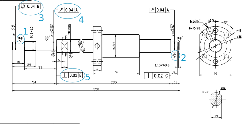
The following drawing is a ball-screw with both ends mechanized and a ball-nut on it.

What is the meaning of the indicated notations?

enter image description here

Context

What is clear to me are:

  • Indications of sizes/distances
  • Angles
  • Parameters of precision/error
  • Diameters

It seem that the little letter (e.g. 2) are related with the values in the box, but I can't understand the meaning. The 1 is completely obscure to me.

$\endgroup$
3
  • $\begingroup$ This is a very broad question. I suggest that you research GD&T and metrology to understand those symbols. We could spend hours/days teaching the concepts $\endgroup$
    – GisMofx
    Commented Dec 1, 2017 at 21:12
  • $\begingroup$ Actually, when one know what to search and has a starting point (thanks to your answer), it does not seem that difficult. $\endgroup$ Commented Dec 1, 2017 at 21:25
  • $\begingroup$ You're welcome. It's fairly straight forward once you understand the basic concepts. If you have a detailed follow up question, I'll be happy to try to answer it. $\endgroup$
    – GisMofx
    Commented Dec 1, 2017 at 21:36

2 Answers 2

1
$\begingroup$

What you are asking is mainly in reference to the GD&T feature control frames on the drawings. Your drawing looks like it's metric, so it may refer to an ISO standard.

If your drawing references a specification, you should research that as this answer would essentially need to teach you GD&T and how to interpret it. Maybe start here: https://en.m.wikipedia.org/wiki/Geometric_dimensioning_and_tolerancing

But there are several resources online.

That being said:

  1. Machined Surface Finish requirement(material removal required) as indicated by the integrated horizontal line below the value.
  2. It looks like a datum callout
  3. Concentricity or Coaxiality(depending on spec and interpretation)(not commonly specified)
  4. Circular Runout(typically used over concentricity)
  5. Perpendicularity

What GD&T does is to clearly define what features are important and how they are to be inspected. They are used to control position and/or form of the part. In your case, that's a rotating shaft so typically the cylinders need to be concentric so they are balanced and aligned for assembly.
$\endgroup$
1
$\begingroup$
  1. This is an indication of surface finish.
  2. This is an indication of a datum
  3. This is an indication of concentricity
  4. This is an indication of runout
  5. This is an indication of perpendicularness

Almost all of these relate to GD&T, which I would recommend you read up on. The fact that you don't know these shows a general lack of knowledge. I would recommend skimming something like ASME y-14.5, or taking a class on drafting.

$\endgroup$

Your Answer

By clicking “Post Your Answer”, you agree to our terms of service and acknowledge you have read our privacy policy.

Not the answer you're looking for? Browse other questions tagged or ask your own question.