3
$\begingroup$

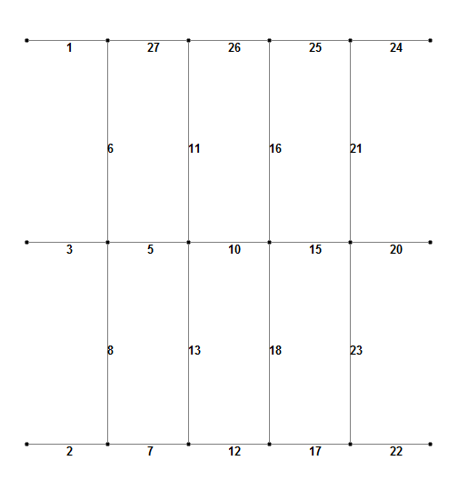
I have trial version of STAAD.Pro software and I am trying to figure out why my calculation are not same as manual one. I have modeled simple structure. But I don't want to have beams 1,27,26,25,24. It is intended that all that beams are one beam and beams 6,11,16,21 are welded to that beam and central beam (there are also beams 3,5,10,15,20 and they are in reality one single beam).

Is that influencing results (Continues load is added to 8 middle beams). I have merged beams 1,27,26,25,24 into single beam , and beams 3,5,10,15,20 into single beam- and beams 2,7,12,17,22 into single beam also - but than it says that I have multiple structures.

Top view of structure

enter image description here

Can someone explain how to model intended?

$\endgroup$

3 Answers 3

3
$\begingroup$

In structural analysis, one represents a real beam (or column, or any other "unidimensional" element) is represented by one or more bars. A bar is defined as a connection between two nodes. If you join all the horizontal bars into one, then you'll be stating that the left-most and right-most nodes (belonging to bars 1 and 24, respectively) are connected, but you'll lose the information regarding how the real beam is influenced by the vertical bars.

There are some programs that allow you to define the real beam as a single bar and then internally break it down into multiple bars when it detects the existence of other elements (such as the vertical bars) which should connect to it (I know Autodesk Robot does this, and there are probably others), but clearly STAAD is not one of them.

Therefore, your current bar layout is correct, since it adequately demonstrates that the beams are connected. You must then define the appropriate releases to describe how the beams are connected.

In this case, however, no releases are required anywhere. Since the horizontal bars represent a single beam, no releases are necessary. This means the bars must deform as one. And the vertical bars are all welded to the horizontals, so they should also deform and rotate in unison. Therefore, no releases are necessary there either.

$\endgroup$
4
  • $\begingroup$ Bars 6 and 8 are in real life welded to central bar as two separete bars. As I see it then it should transfer all 3 forces and 3 moments. (fixed connection betwen bar 6 and central bar - , and bar 8 and central bar) Is this correct. Thank you for your answer ! $\endgroup$
    – Sysrq147
    Commented Jul 31, 2016 at 19:22
  • $\begingroup$ Welded connections are usually simplified into hinged (moment release) connections. A more correct representation would be a "partial fixity" connection, which behaves like a spring, allowing for differential rotations but resisting them and therefore transferring some moment to the other bar. Unfortunately, I don't know how to obtain the stiffness coefficient for such a connection. Nor do I know if STAAD even has them. $\endgroup$
    – Wasabi
    Commented Jul 31, 2016 at 20:01
  • $\begingroup$ I have trouble understanding that welded connection is hinged and not fixed. :) In some calculation I have seen that they are calculating maximum moment on beam that is welded betwen two beam as M = (q*l^2)/24, treating beam as fixed on both ends. That is why I am confused a bit. $\endgroup$
    – Sysrq147
    Commented Jul 31, 2016 at 20:05
  • $\begingroup$ @Sysrq147: While I am a civil engineer, I've worked almost exclusively with concrete, so my knowledge of steel is basically what I learned in school. Your question regarding how welds can be considered hinges was one I had as well, so I recently asked in the chat and the answer is simple: they aren't. You are correct, they are considered fixed. I apologize for the misinformation. I've also edited an answer to a previous question of yours where I stated welds were hinges as well. Once again, my bad... $\endgroup$
    – Wasabi
    Commented Aug 2, 2016 at 13:11
2
$\begingroup$

In short, by having them each as single members or beams should not be influencing the result provided that you have connected them together as fully fixed/welded (this is the member end condition - there should be no releases at the ends of the members so that the software will treat the individual members as one continuous member).

Combining them into one single member is not the correct way to model it. They need to be individual members with the correct member end conditions.

As to why your manual calculations are not matching the software is anyone's guess - either your calculations are wrong or you're not modelling it correctly in the software. Perhaps you should provide your calculations or more info about the structure and how it is both loaded and supported, then we can probably help you further.

$\endgroup$
0
0
$\begingroup$

I think it is imperative to first determine if the cross-beam to main-beam connection is a moment-(resisting-)connection. I am not sure if the cross beams are (or need to be) moment-connected to the main beams.

In the given case, beams 6,11,16,... 8,13,18... appear to be cross beams that carry local floor loads. It is not generally necessary to make them moment connected. Usually they are welded to a pair of angles, which will fit to some pre-drilled holes on the web of the main beams for ease of erection. Individual beams can be transported in different trucks. If this is the case, the connection is usually considered a pinned connection. The following is what they look like: Typical Steel Connections (scroll to about 1/3 down the page and look for beam-to-beam connections)

If they are "welded" to the main beams and are expected to transmit moments, they would likely look like these, and obviously cost more in fabrication: Moment resisting connections (scroll to the last fifth of the page to see beam-to-beam connections).

There is also a complication with perpendicular beam-to-beam moment connections in the sense that the beam-depths are usually different. In this case, the main beams are likely to be deeper than the cross beams. So again, moment connections are not usually called for. In any event, if beam 6 is moment connected to beams 1 and 27, the latter will provide very little torsional resistance, so I doubt if it is worthwhile to have them moment-connected.

One more reason that the cross beams are not moment-connected to the main ones would be if all these beams are welded in the shop, it would become a single piece that may not be transportable by trucks to the building site using highways. On the other hand, welding in the field would create extra quality assurance expenses, x-ray inspection, etc.
$\endgroup$

Your Answer

By clicking “Post Your Answer”, you agree to our terms of service and acknowledge you have read our privacy policy.

Not the answer you're looking for? Browse other questions tagged or ask your own question.