0
$\begingroup$

So I have to create a control system simulation from scratch for the following scenario. For a bicycle-like system, there is a motor attached directly to the rear wheel. From here, the goal of the control system is to use the motor to maintain a constant speed, rejecting a small disturbance force pushing against the system from the front.

With the context out of the way, I've been struggling to create the transfer function that allows me to get the linear velocity from the rest of the system. So far, I've tried the process vaguely outlined in the picture below, where I've tried to rearrange a DC motor system to output torque instead of angular position, and then scaled that torque into a linear force before applying that force to the mass and air resistance to get the speed output.Handwritten TF block diagram
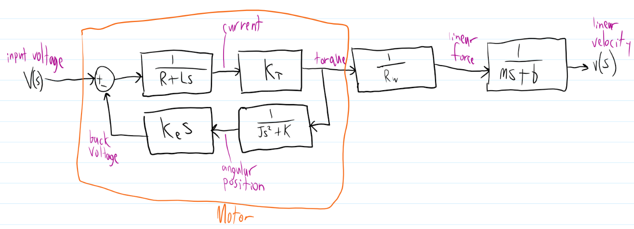
(R and L are the internal resistance and inductance of the motor, respectively, Rw is the wheel radius, m is the total mass of the system J is the inertia of the rear wheel, b is the air resistance drag, Ke and Kt are motor coefficients and K is the constant for a tiny spring-like component. 1/(Js^2+K) is supposed to be the inertial load of the motor, and although I'm starting to suspect the spring component isn't necessary the system acts worse without it.)

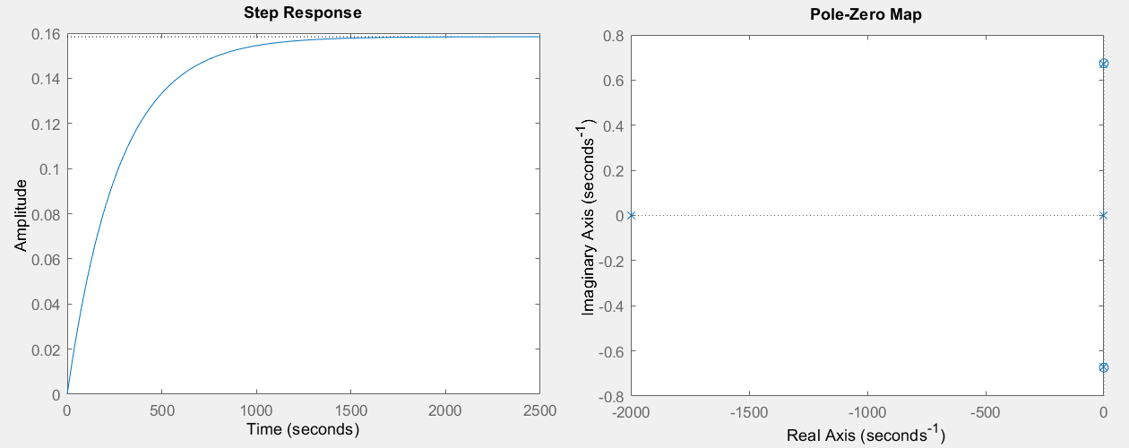
The issue is that, when I try to simulate this open-loop system in Matlab, I get a rise/settling time that's almost 100 times larger than I'd consider acceptable for this kind of system. The poles and zeros aren't exactly confidence-inspiring either, with unstable zeros and poles that hang a fraction of a unit from the imaginary axes. None of my experimenting with controllers, closing the loop or tweaking my imperfect input variables has done anything to change the overall structure of the output.Matlab plots
So is there an easier or well established method to create the kind of transfer function I'm looking for? I've been hammering away at this for long enough that I'm starting to think the process I tried isn't fixable.

With everything said, I apologize if my terminology is incorrect or I'm missing something super simple. Control systems are not my forte, and I've only started with them a couple of months ago. Thank you so much for your time!

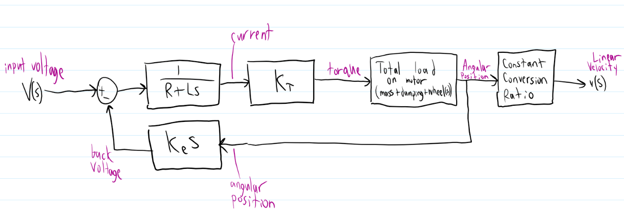
Edit: Here are the plots requested. These definitely don't look right. enter image description here Also, here's a diagram that represents what I'm trying to refer to in my second comment. enter image description here
$\endgroup$
1
  • $\begingroup$ The last block diagram appears to be on the right track provided that you are allowed to use the no-slip-between-tyre-and-road assumption. $\endgroup$
    – AJN
    Commented Dec 12, 2022 at 13:14

1 Answer 1

0
$\begingroup$

Too long for a comment.

  1. As you suspected, a spring component in the wheel transfer function is not justified (while a viscous force can be justified). If you cannot identify a physical mechanism for a restoring force / torque (i.e. spring force), it will have to be removed.
  2. From the orange rectangle, it can be seen that the angular position and angular velocity for a fixed torque depends on the wheel inertia only. One would assume that for a bicycle like device, the over all mass of the system would also be involved. Why would a larger $m$ of the vehicle not affect the motor angular position ?
  3. Continuing the above point, if the wheel does not slip (which might be a reasonable assumption to make for many systems), the relation between motor angular position and angular velocity and linear distance and linear velocity are a fixed ratio. One would model it as a system with gears using reflected mass or inertia etc. Are you familiar with modeling systems involving gears ?
  4. Can't comment on the rise time etc. as it depends on the values used for the variables also.
  5. Can you plot the angular position and velocity of the wheel also along with the linear velocity ? Please clearly label the plots.

edit

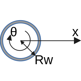
Under assumptions like no-slip between tyre and road, no flexing of the body or drive train, we can write equations as follows.

tyre and symbols

$$ x = R_w \cdot \theta \qquad \text{no slipping condition}\\ \implies \color{blue}{\frac{d^2 x}{dt^2} = R_w \frac{d^2 \theta}{dt^2}}\\ \frac{d^2 x}{dt^2} = f/m\\ \frac{d^2 \theta}{dt^2} = \sum{T}/J = \frac{T_{\text{electrical}}}{J} \color{red}{\pm} \frac{f\cdot R_w}{J}\\ \implies \frac{d^2 \theta}{dt^2} = \frac{T_{\text{electrical}}}{J} \color{red}{\pm} \frac{m \cdot R_w \cdot R_w}{J}\cdot \frac{d^2 \theta}{dt^2}\\ \implies \frac{d^2 \theta}{dt^2} \color{red}{\mp} \frac{m \cdot R_w \cdot R_w}{J}\cdot \frac{d^2 \theta}{dt^2} = \frac{T_{\text{electrical}}}{J}\\ $$

Continue rearranging the equation till you get $\frac{d^2 \theta}{dt^2}$ on LHS. The complicated stuff on the RHS denominator should be the effective inertia which includes effect of mass.

You might have to re derive along similar lines to be able to include viscous forces or any other forces into the equation.

edit 2

Continuing the rearrangement, $$ \frac{d^2 \theta}{dt^2} = \frac{T_{\text{electrical}}}{J + m \cdot R^2_w}\\ \implies J_{\mathrm{eff}} = J + m \cdot R^2_w \qquad \text{looks quite reasonable} $$

The instantaneous centre of rotation is the point of contact between the wheel and the road. The inertia about this point is given by the parallel axis theorem. The effective inertia derived above also looks to be the same expression.

$\endgroup$
8
  • $\begingroup$ I edited my post above to include the plots you asked for so I don't have to make a separate post. I had to recreate my model in Simulink, which isn't behaving exactly the same, but it should be close enough. If you wanted to confirm that things aren't working right, this is it. The angular position definitely shouldn't be leveling off like that. I am familiar with gears in as much as T1/T2 = R1/R2. I've never considered seeing those other transforms as gears, but I guess it wouldn't be so different from how I divided torque from radius to get linear force. Continued in next comment. $\endgroup$
    – Delstrom2
    Commented Dec 11, 2022 at 22:30
  • $\begingroup$ So that leaves the last major couple of points, regarding the reflected mass on the torque. If you'll give me a moment to confirm, I can tell that the load from the mass and damping needs to be represented as a load in the motor system, not just at the end of the system like I have it. Does this mean that I should rearrange the system and have the entirety of the load represented in the motor's inertial load component, find the angular position, then convert that to linear velocity instead? If so, that only leaves me with the question about how to convert the linear load into an inertial load. $\endgroup$
    – Delstrom2
    Commented Dec 11, 2022 at 22:51
  • $\begingroup$ Editing post is the standard method to add new info to the question. $\endgroup$
    – AJN
    Commented Dec 12, 2022 at 12:27
  • $\begingroup$ Yes. I think you have it right about presenting the linear load (converted to rotary load) presented to the motor model. Conversion from linear to rotary should be straight forward using the radius of the wheel (or its square) as the conversion factor. Let me see if I can put it in clear terms and edit my answer to include that. $\endgroup$
    – AJN
    Commented Dec 12, 2022 at 12:30
  • $\begingroup$ You are right in that, the angular position should not be leveling off. that is because the spring force modeled on the motor is getting stretched and providing a restoring force and ending up cancelling the electrically generated torque in steady state. $\endgroup$
    – AJN
    Commented Dec 12, 2022 at 12:33

Your Answer

By clicking “Post Your Answer”, you agree to our terms of service and acknowledge you have read our privacy policy.

Not the answer you're looking for? Browse other questions tagged or ask your own question.