a short disclaimer that for me mechanical engineering is a hobby. Please be gentle with me, even if there may be an obvious answer. The main reason for asking here is that searching for the topic you end up with 99% content on cars which does not translate well for my application.
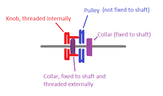
I'm currently designing and building my first own equatorial mount for astronomy. I'm actually done with most of it and now realized that I need a clutch on each axis. There are two axis in play here which can be considered identical from the requirements below. The axis are driven by a pulley in my design. So the axis currently would look like this from the side:
     P
-B---P-------B-
     P
So a bearing (B) on either side that sit inside the housing allowing the shaft to rotate and the pulley (P) transferring force to rotate the axis at the desired speed. The shaft diameter is currently 35mm. This layout can be modified to accommodate the clutching mechanism.
Here's the mode of operation of the axis:
setup phase:
- motors are off, no force transmission happening
- the user needs to be able to operate the clutch (screw something, pull something, shift a lever) which disconnects the pulley from the axis
- the axis then freely moves supported by the bearings
- FYI: the user uses the freely moving axis to balance the payload (telescope) so that there is no moment applied in any orientation of the telescope
operating phase:
- the user operates the clutch again to connect the pulley to the axis again
- motors are switch on
- the axis rotates at 1 revolution per day (~15 arcsec/sec) to 4 degrees per second for positioning around the sky
- the axis is driven in BOTH directions for positioning around the sky
- you probably guessed it already that the clutching mechanism needs to transfer the force reliably in a lot of orientations depending on where the telescope is pointing in the sky
- while in operating phase the clutch would only be disengaged in an absolute emergency, it's probably good enough to just rule our this scenario as a user can switch off power faster
additional wishes but not strict requirements:
- for space reasons I would like to have one solid shaft, if that were not the case the actual shaft length would be significantly reduced and I'm worried about the deflections from the payload
- the clutch should not introduce backlash - I have taken great care in the design to eliminate it everywhere so would be a shame to introduce it here. Screams "something based on friction" to me.
- ideally I would like to buy something "off the shelf" but not necessary if the mechanism is simple
I partially disassembled my commercially bought mount and it uses a friction based clutch. Something that I also had in mind. Unfortunately I couldn't quite understand how it actually works without disassembling it completely. I didn't want to do that because I actively use it for my astrophotography hobby. Basically the user screws an end stop onto the shaft that has a felt washer on the inside. You screw until you can't go any further and the clutch is engaged. Force is transferred from a worm gear to the shaft. If you unscrew the shaft rotates freely. I somehow suspect that the worm gear is actually not sitting on the shaft (really difficult to see unfortunately), but the end-stop you screw on is actually what connects it to the shaft. I don't understand why this doesn't axially displace the worm gear or why the force applied doesn't unscrew the end-stop again.
I saw another design that mentioned that they seem to use something where bearing and clutch are combined as one item. I tried to find out what that would be / where how to buy such a thing but ended up with ... you guessed it: car content.
How would you go about solving this?
