0
$\begingroup$

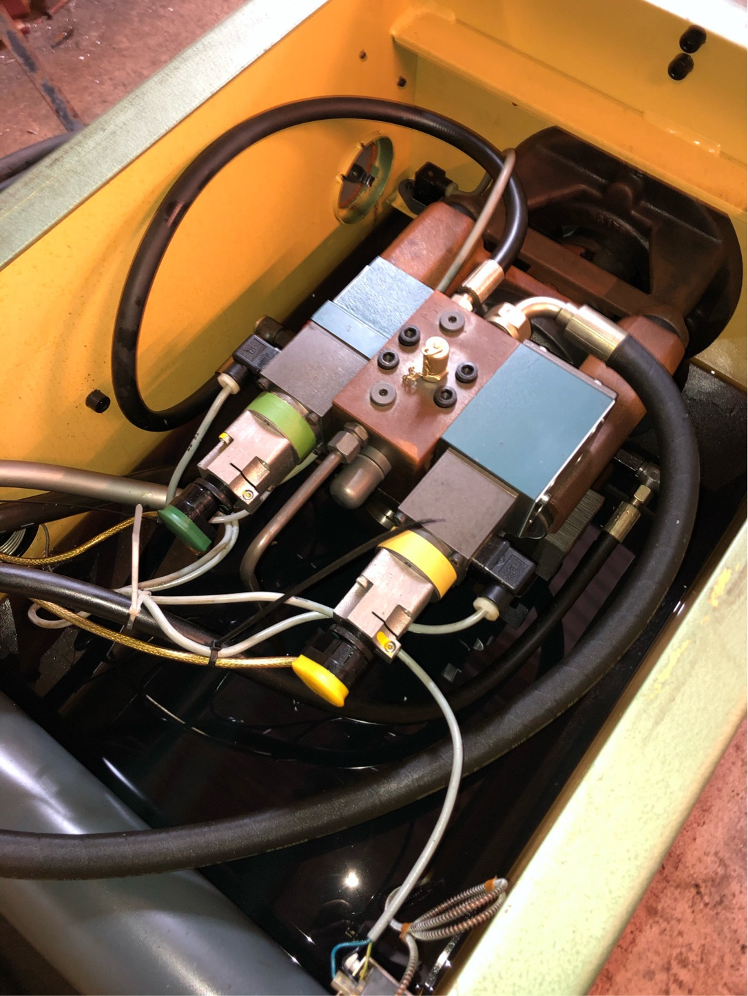
I am building a new control system for an injection moulding machine, the last part I am trying to work out is the main pump.

It has two proportional valves on the output, one labelled throttle valve and one labelled pressure limiting valve.

The throttle valve is connected between the pump outlet and the pressure limiting valve is connected between the pump control line and the tank return.

I think that you use the throttle valve to control the pump pressure and use the pressure valve to control the bypass pressure which is just like an energy saving thing. Is this the correct way of thinking?

The main question is though was voltage is do I use to control the valves and what is the pinout for the 3 pin feedback connector on the end on each valve?
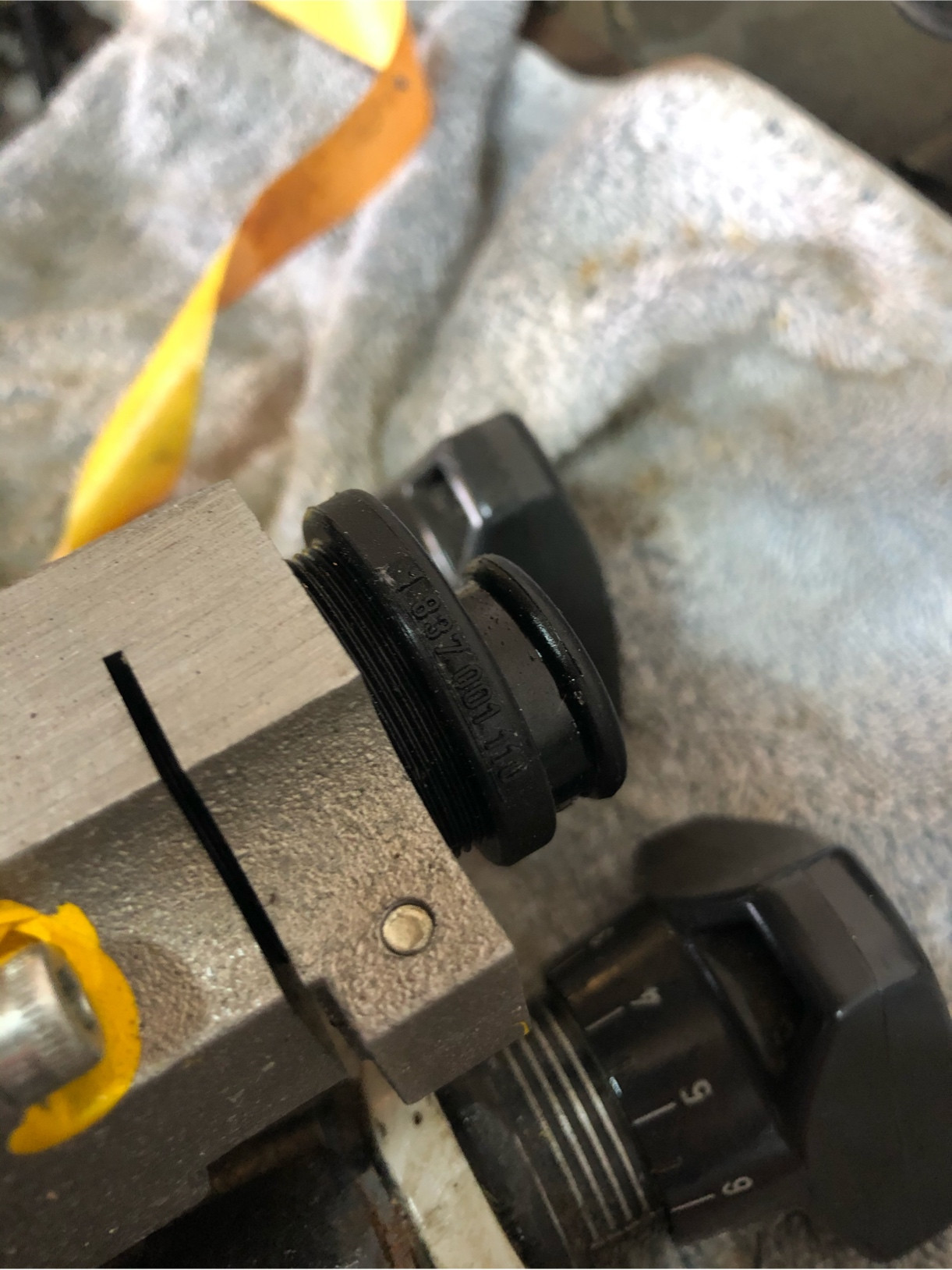
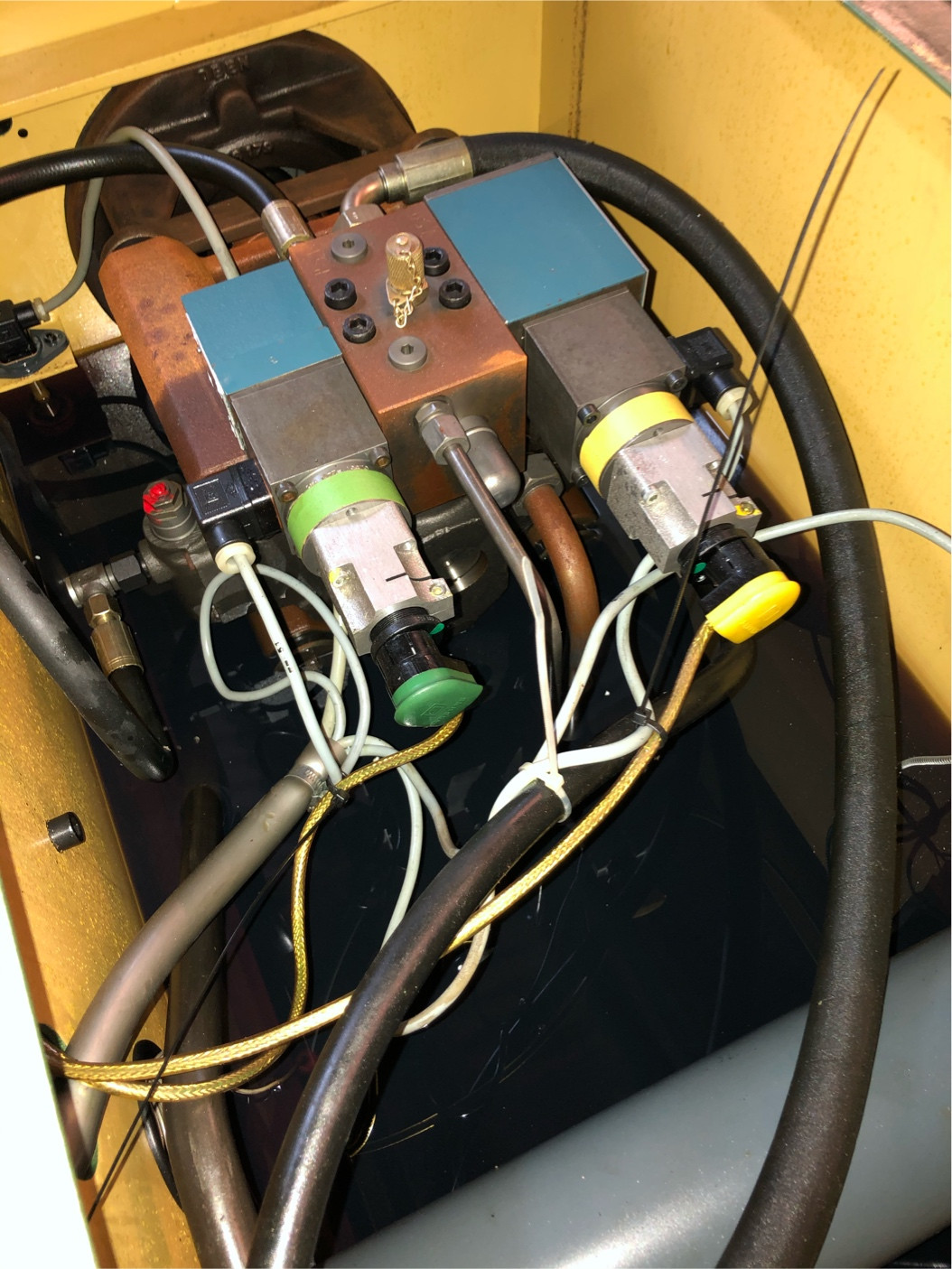
Pictures of the pump and valves: enter image description here enter image description here enter image description here

$\endgroup$
3
  • $\begingroup$ I think you're only showing the mechanical valve label. The solenoids, if they're one of many options, may have their own labels. Usually these will be matched with the control card and require some calibration as the valves may be non-linear and may have a high control offset before they start to open. $\endgroup$
    – Transistor
    Commented Nov 21, 2020 at 23:24
  • 1
    $\begingroup$ Top 2 images showthe hydraulic functionality. Look at the solenoid itself, maybe 12V, 24V or 110VAC or 240 VAC. Photograh the correct part in detail. $\endgroup$
    – Solar Mike
    Commented Nov 22, 2020 at 4:27
  • $\begingroup$ For high quality control of proportional-solenoid-valves, you want to (1) control current, not voltage. (2) add a dither waveform to the current, to overcome the hysteresis (essentially by forcing the hysteresis action to happen at a higher frequency where it gets damped out mechanically in the output flow). Some poking around with electrical tools like scope and signal generator can be massively helpful if you do not have a ready-made valve current controller. $\endgroup$
    – Pete W
    Commented Jan 11, 2021 at 15:25

1 Answer 1

0
$\begingroup$

After some research, I found out that the valve is 0-24v DC and the output from the feedback sensor is 0-20ma. They are designed to work with a Bosch controller but can be used with any PLC if an amplifier with the correct gain is used.

$\endgroup$

Your Answer

By clicking “Post Your Answer”, you agree to our terms of service and acknowledge you have read our privacy policy.

Not the answer you're looking for? Browse other questions tagged or ask your own question.