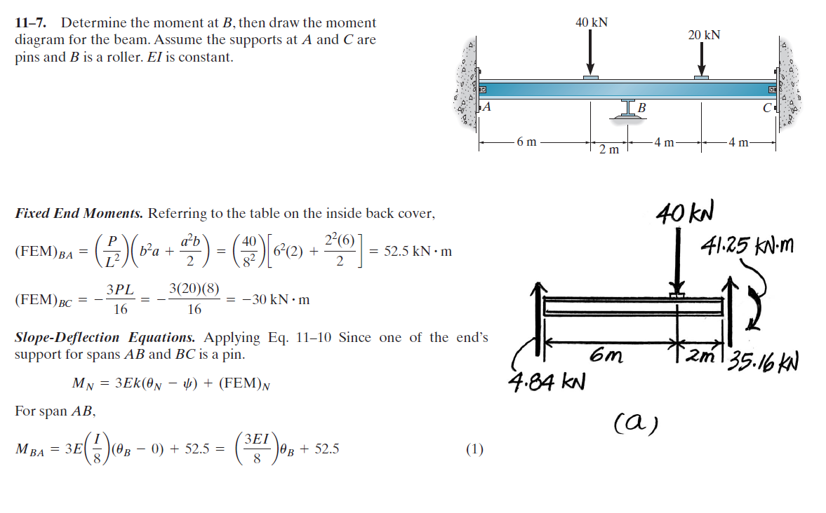
Why the Fixed End Moment (FEM) for BC is 3PL / 16? It's clear in the first figure that that when one end is fixed, while the another end is pinned, then the fixed end moment is 3PL /16 ... But for the span BC, we could see that B is the roller and C is the pinned connection, there's no fixed support in the span BC
3 Answers
If you look at the structure (ignoring the loading), it is symmetrical: two spans of equal length, with pins on the extremities and a roller in the middle. It is also a hyperstatic (or statically indeterminate) structure, with more unknowns than static equilibrium equations.
You might therefore be tempted into simplifying this model into a single fixed-and-pinned beam. After all, a symmetrical load on both spans will cancel out the rotation at B, and a point with bending and no rotation is equivalent to a fixed support. So why not simplify the model into a single span? Sure, it's still hyperstatic, but it's a classic condition with known reactions as given by your tables.
Well, obviously the problem is that, in this case, the loading isn't symmetric. So what do you do?
You ignore that little detail and momentarily pretend that you are in fact dealing with two fixed-and-pinned spans. You then calculate the moment reaction at the "fixed" point B for each span. You then use slope-deflection equations to figure out what the actual rotation around B is and use that to recalculate your reactions.
So let's take this one step at a time.
Assume AB and BC are pinned-and-fixed beams and calculate the moment reaction at B in each case using your tables:
$$\begin{alignat}{4} M_{B,AB} &= \dfrac{P}{L^2}\left(b^{2}a + \dfrac{a^{2}b}{2}\right) &&= 52.5\text{ kNm} \\ M_{B,BC} &= \dfrac{3PL}{16} &&= -30\text{ kNm} \end{alignat}$$
Note that $M_{B,BC}$ used the top-right case from your table since the load was centered, while $M_{B,AB}$ used the next one below since the force is off-center. Also note that the structure in both cases is the same: a fixed-and-pinned beam.
Also note that the results for $M_{B,AB}$ and $M_{B,BC}$ aren't equal, which tells you that the assumption that point B was the same as a fixed support with no rotation was incorrect.
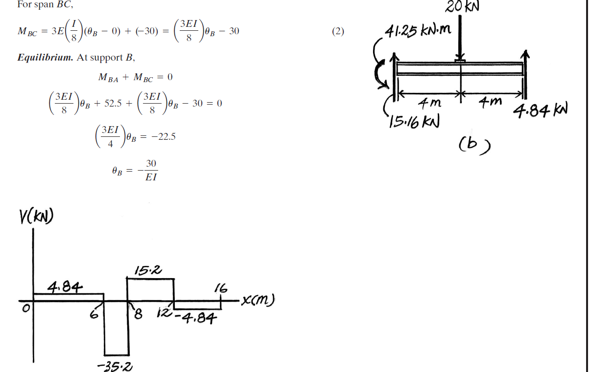
You therefore use the slope-deflection equations to figure out the relationship between bending moment and rotation for each span, use them to calculate the actual rotation around B, and then use that to calculate the actual bending moment around B:
$$\begin{alignat}{4} M_{B,AB} &= \dfrac{3EI}{8}\theta_B + 52.5 \\ M_{B,BC} &= \dfrac{3EI}{8}\theta_B - 30 \\ M_{B,AB} &= M_{B,BC} \\ \dfrac{3EI}{8}\theta_B + 52.5 &= \dfrac{3EI}{8}\theta_B - 30 \\ \therefore \theta_B &= \dfrac{-30}{EI} \\ \therefore M_B &= \dfrac{3EI}{8}\theta_B + 52.5 &&= -41.25\text{ kNm} \\ &= \dfrac{3EI}{8}\theta_B - 30 &&= -41.25\text{ kNm} \end{alignat}$$
(I just calculated $M_B$ twice to show that you can use either of the equations to find its value, obviously)
With that you have the actual moment at B and have solved the problem.
The fixed end moment is the moment at the joint if it were held to not be rotated, or if it were fixed. This is why the moment is 3PL/16, because B is "fixed" and C is pinned.
The problem mentioned that support A and C are both pins, therefore you should use the modified slope-deflection equation.
-
$\begingroup$ This doesn't really answer the question of why to use $\dfrac{3PL}{16}$ in this case, given that there are no fixed supports. Or of what's the relevance of those calculations before the slope-deflection equations. $\endgroup$– WasabiCommented Jun 21, 2018 at 23:54


