1
$\begingroup$

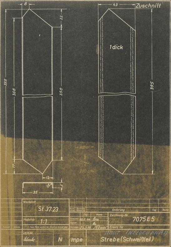
I am working in Inventor LT 2021 which means I do not have access to the sheet metal tool. Which would have been great as the example I am working on is sheet metal. The example drawing I am working with is located here. I am assuming the part on the left is the cut from the sheet metal with those interesting -/- markings being the limits of fold line? According to google translate "Zuschnitt" is "Cutting"

enter image description here

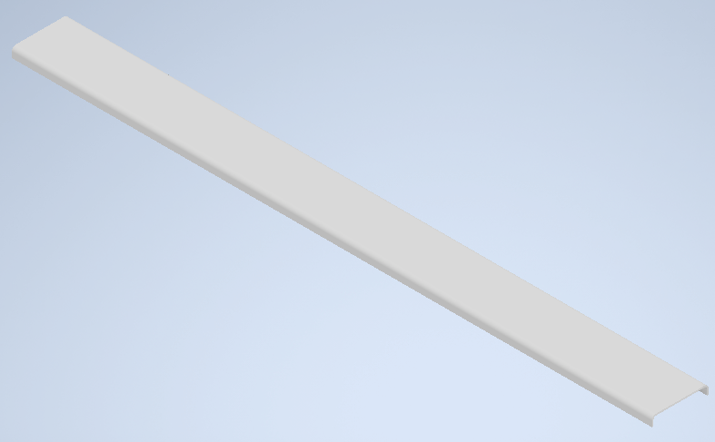
I started out by creating the end view and then extruding it the full length of the object.

enter image description here

enter image description here

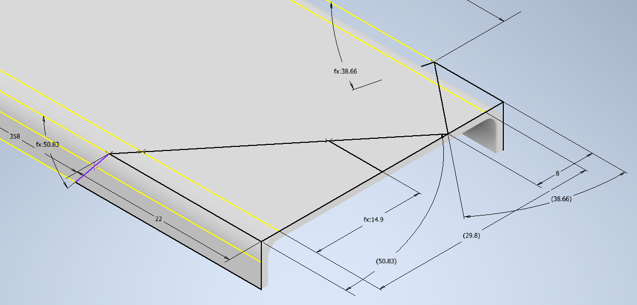
I then sketched on the top surface the angle cuts with the thought of extruding and deleting the small triangles. I then sketched the continuation of the angled cut on the face of the short legs.

enter image description here

This is when I realized that the second extrusion would lead to an "ugly" transition to the cut from the first extrusion. The face/plane of the cut should twist as the sheet metal was folded.

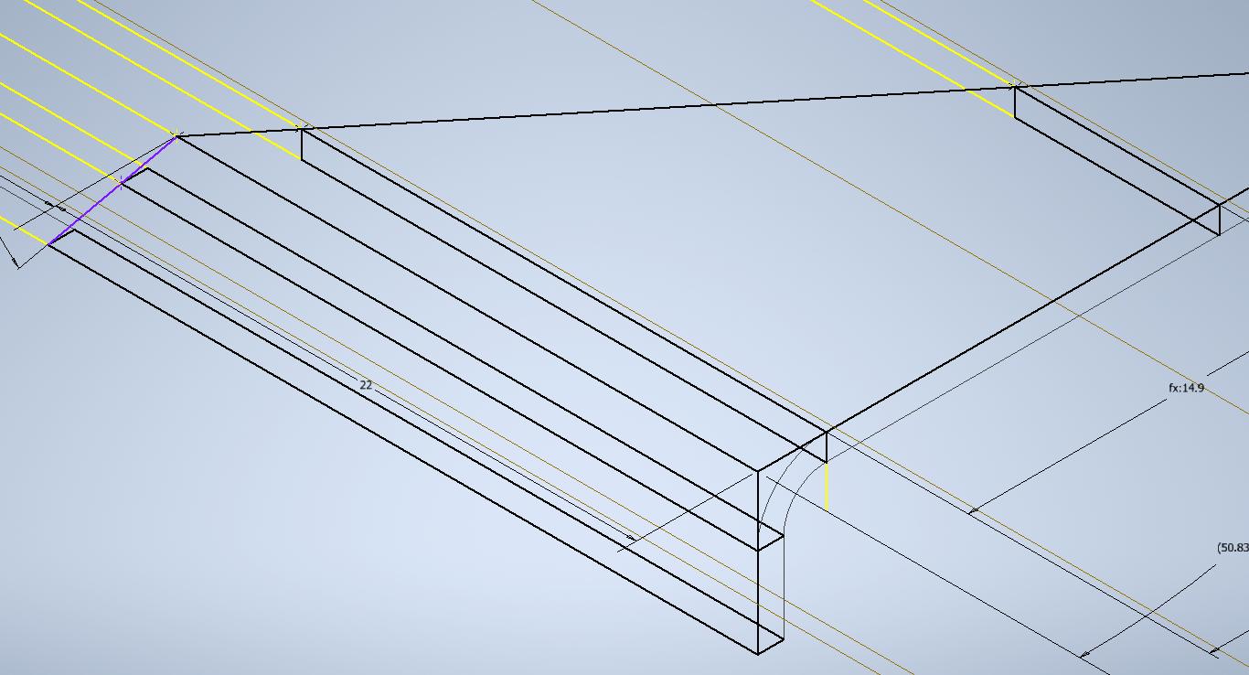
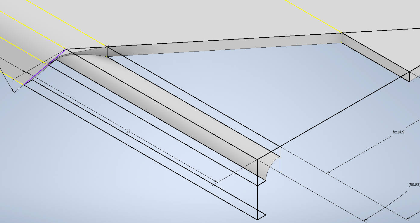
I attempted to work around this with loft. I drew 4 sections the area of the material to be removed at the base of the leg, then just before the curve for the fold line, then just after the fold line, then again mid way across the piece.

enter image description here

in my first attempt I simply picked the 4 areas in order and things did not go well. The loft buldged in ways really not desired. I attempted to add tangency to the start and end pieces, but that failed. I then tried doing 3 separate subtractions lofts. I had a 2 out of 3 success rate.
I basically lofted the 2 sections before and after the bend successfully, but the loft through the bend did not work. I even added rails which were the end edges of the original piece as it went around the corner. I do not know how to get the right corner rail lines at the cut corner.

enter image description here

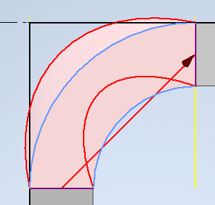
The above is an end view of the loft with the red lines being generated at the cut end and the blue lines being the rails at the other end. The difference between the two inside curves results in left over material as seen below.

enter image description here

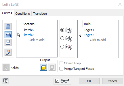
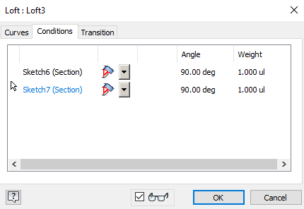
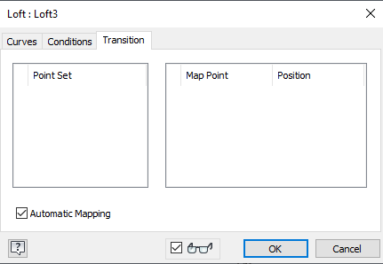
The setting in loft were as follows:

enter image description here

enter image description here

enter image description here

How can I make this piece have a smoother transition within the limitations of inventor light 2021 (ie. no sheet metal tools)
$\endgroup$
3
  • $\begingroup$ Is knowledge.autodesk.com/support/inventor/learn-explore/caas/… available in LT2021? $\endgroup$ Commented Nov 8, 2021 at 11:52
  • $\begingroup$ @JonathanRSwift *&#@*$%!!!! yes it is...it was hidden in a drop down from the main menu! Thank you. Learning moments like these tend to make things sink in. $\endgroup$
    – Forward Ed
    Commented Nov 8, 2021 at 12:57
  • $\begingroup$ @JonathanRSwift put that in as an answer and optionally expand on why this is not intended for use with sheet metal as stated in the article and I will mark it as the answer. $\endgroup$
    – Forward Ed
    Commented Nov 8, 2021 at 13:23

1 Answer 1

1
$\begingroup$

It is possible to bend solid bodies within Inventor LT using the "Bend Part" command.

https://knowledge.autodesk.com/support/inventor/learn-explore/caas/CloudHelp/cloudhelp/2019/ENU/Inventor-Help/files/GUID-98FDE447-C0A7-4694-ABD3-BA19A329DDF6-htm.html

Using this will allow you to create the flat pattern per the right hand view, and to bend it using sketched definitions for the start of the bend per the -/- lines, which you rightly assume define the transition between flat and curved sections on the final part.

This is not recommended for use in sheet metal applications since it does will not automatically generate a flat-pattern configuration, or bend lines etc. to be automatically imported in a 2D drawing. The warning on the help page is there primarily to make it clear that "Bend Part" is not the same as "Bend".

"Bend Part" is in some ways more powerful than "Bend", in that it is able to stretch/modify more complex bodies. For example, any attempt to "Bend" the part in your drawing in a direction perpendicular to the long folds would fail to calculate using "Bend". With power comes responsibility, though - it's also not error checking for if something is possible in sheet metal. In real life with a sheet metal part, this would be difficult to achieve due to the stiffness from the existing folds having to 'stretch' - you would need to cut a relief notch in them first, which if done in CAD, would allow the "Bend" tool to work again. So, for sheet metal, using "Bend" can help dissuade you from creating parts that cannot be manufactured.

$\endgroup$

Your Answer

By clicking “Post Your Answer”, you agree to our terms of service and acknowledge you have read our privacy policy.

Not the answer you're looking for? Browse other questions tagged or ask your own question.