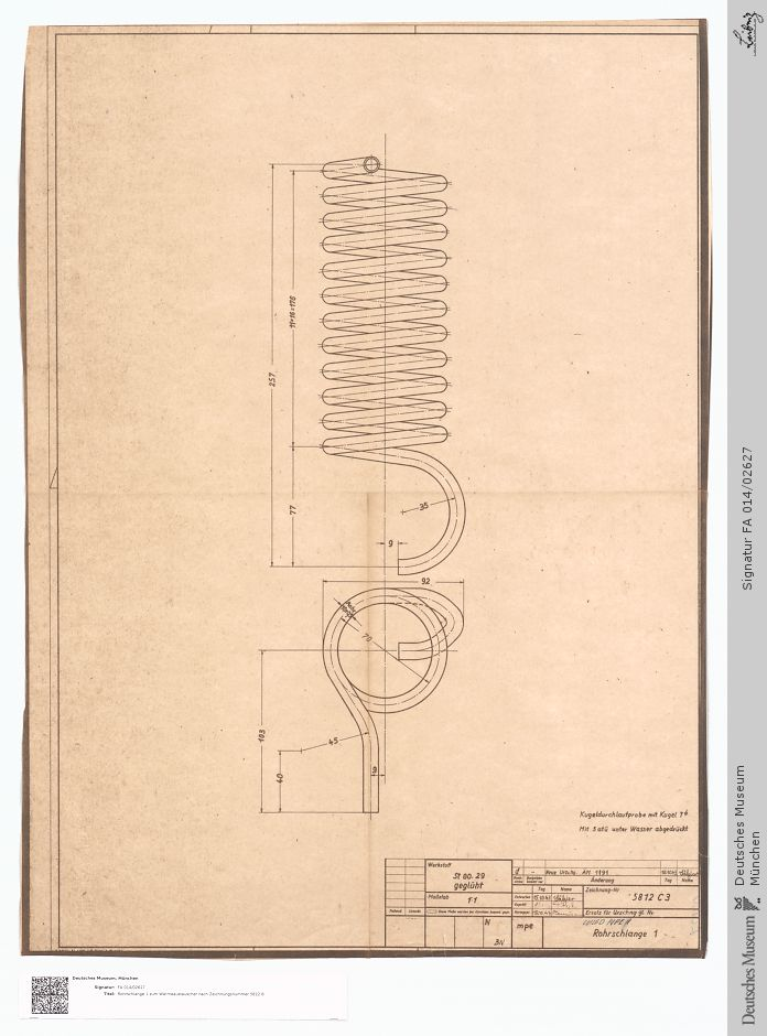
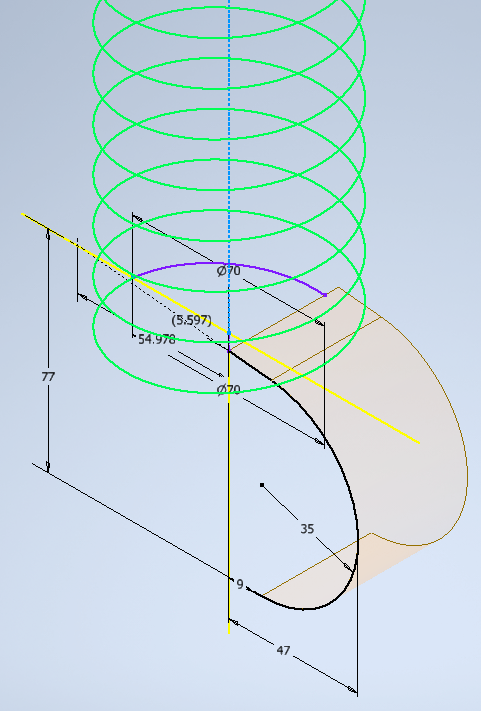
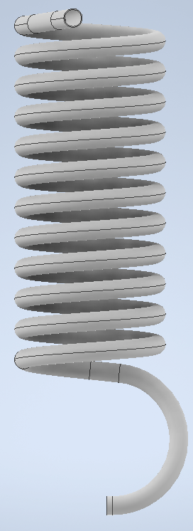
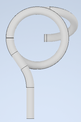
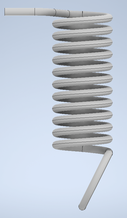
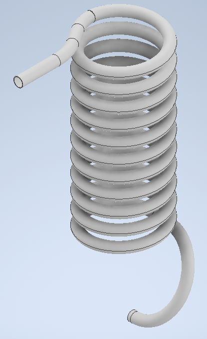
BACKGROUND: I had previously dealt with 2 pipe coils with oddly bend ends. for the most part I was able to use the coil tool and was able to line up a bunch of 2D sketches to complete the odd end bits. When I was done I noted that while what I created matched the views I was working with perfectly, they also had kinks in the pipe that should not be there. I figured this was a mainly a result of the pipes circles remaining vertical instead of perpendicular to the end of the coil path. I figured when I learned more I would go back and try and fix things.
I then stumbled on this drawing and 3 more just like coming up so I figured I should bite the bullet and find out the right way of doing things.
So in order to avoid the kinks in the pipe where various sections meet, I thought I would plot the continuous center line for the whole thing, place the pipe cross section at the start then sweep the cross section along the path. Sounded simple enough.
WHAT WAS TRIED
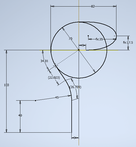
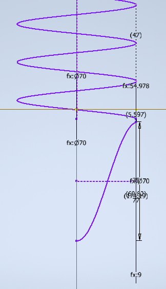
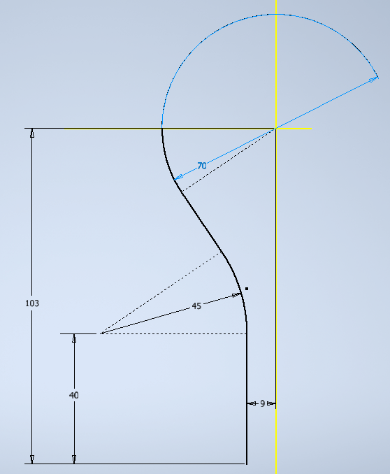
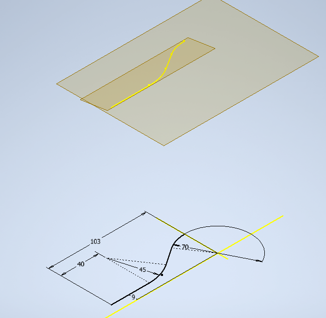
I started out by plotting the centerline of the top view, adding some key points, and transferring some information from the front view to complete.
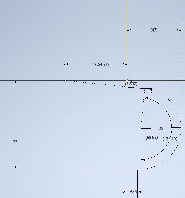
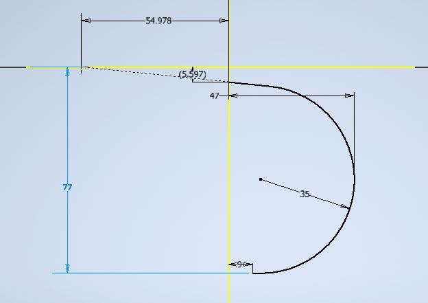
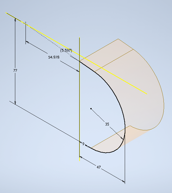
I then proceeded to draw the bottom end of the front view. I assumed that the slope of the helix continued to the tangent point at the quarter mark and then be tangent with the 35 radius circle. This turned out to NOT be true as the line never intersected with the circle.
My next step was to essentially uncoil the 1/4 turn of the helix. I simply used PI/2*Radius to get the arch length. The thought being I would get the start point of the line that would be tangent to the circle. Though as I just typed that I realize my simple uncoil may not have been correct as it did not account for the helix's slope, just the circle. Though probably close enough for the time being.
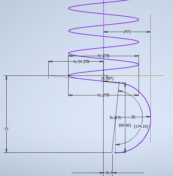
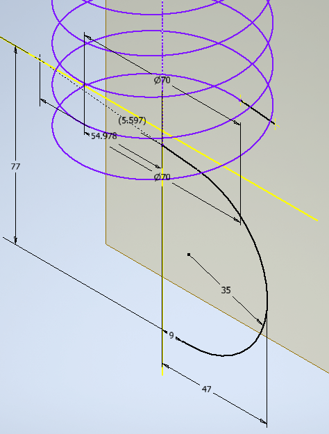
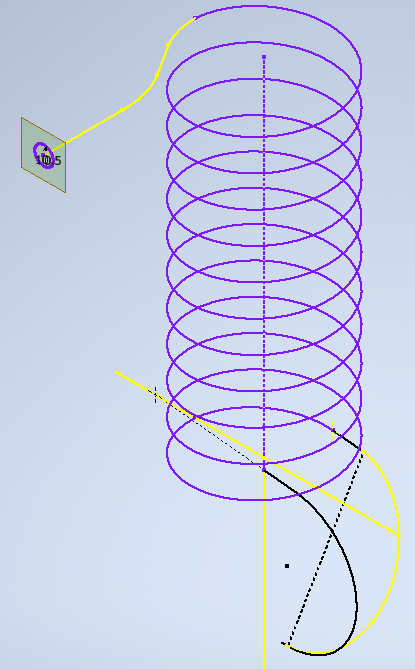
My next step I jumped into 3D sketch for the first time and discovered the Helical Curve tool which I thought would make life easier. The first helix I made was the main coil, and it worked great...it never had to be attached to anything. The next helix I made was the last bottom 1/4 turn at a slightly different pitch (4*Fx:5.597). I then attempted to make a 3rd helix which just plain failed in a major way (others may have failed, but not that obvious if they did). The third helix is almost a half turn going from the edge of the main spiral towards its center (35 radius).
So it looks pretty good in front view. Everything lines up where it needs to be. Even the right view looks pretty good.
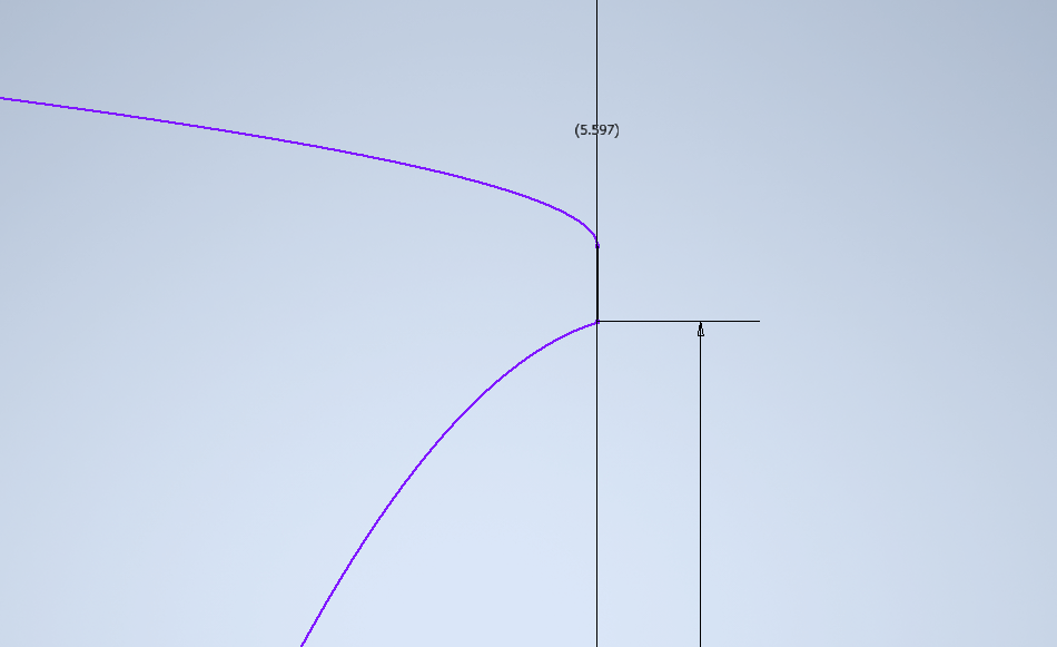
Though I did notice a bit of a kink where the tangent met the start of the third helix.
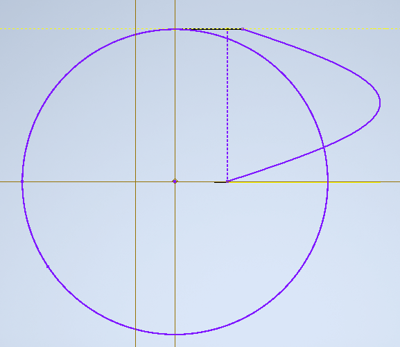
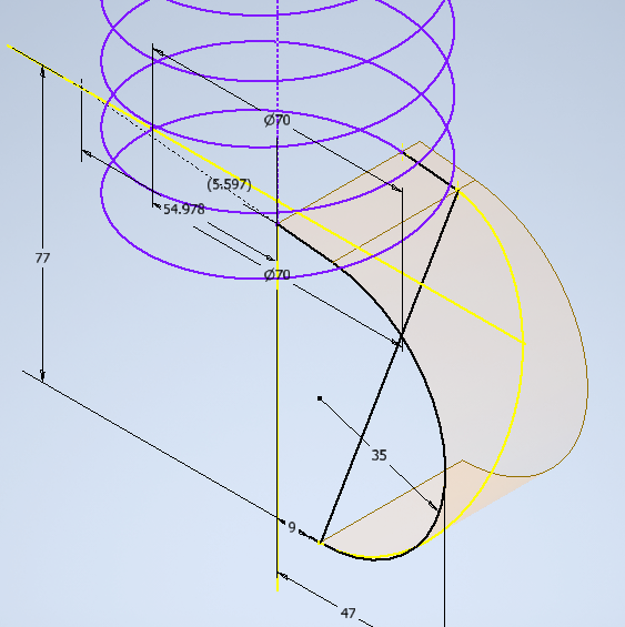
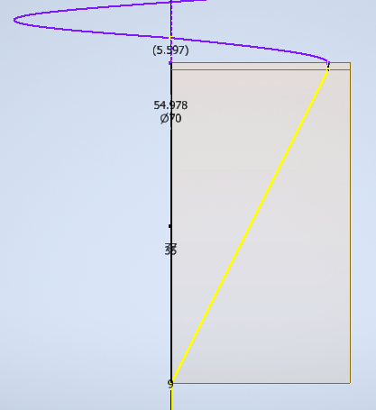
I was expecting the bottom helix to come off more like the top. However this was not where I really noticed the problem. I really noticed the problem in top view. The sideways parabolic like shape in the top right quadrant starts and ends at an angle to their tangent lines.
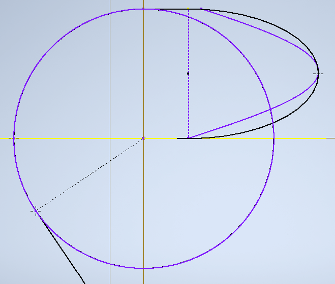
I believe they should be "more" like my initial sketch superimposed below. I say more because my sketch is not perfect. The sketch assumed it was a 1/2 turn when in reality its slightly less. I used a single ellipse when creating the sketch.
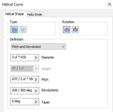
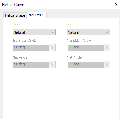
I used the following parameters for creating the third helix:
QUESTION
What is the proper way to model coiled pipes like this?
How do I fix the kink at the start and end of helix 3?
