0
$\begingroup$

Hope you all are doing good.

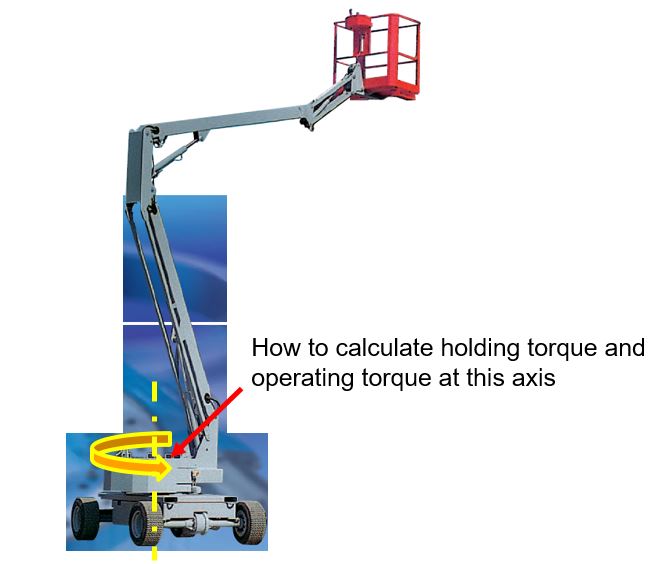
Can anyone please guide me on how to calculate the different torques at the base as shown in the image? please click here for image
Thank you for your time and help.

$\endgroup$
5
  • 1
    $\begingroup$ Since there are no horizontal forces coming into play in the above figure (since the only force is the weight of the structure), so I don't think there should exist any torque onto the base. $\endgroup$ Commented Oct 26, 2021 at 13:32
  • $\begingroup$ Shape of the arm won't matter, but the distance of the load from the base will. Think about why cranes tip over.... $\endgroup$
    – Solar Mike
    Commented Oct 26, 2021 at 13:35
  • $\begingroup$ @RameezUlHaq what if I want to rotate the whole thing from the base, in that case torque will exist onto the base. $\endgroup$
    – user35513
    Commented Oct 27, 2021 at 15:08
  • $\begingroup$ @SolarMike thank you for sharing but I think your point is more related to the tilting moment and not with torque. $\endgroup$
    – user35513
    Commented Oct 27, 2021 at 15:09
  • $\begingroup$ But when you are rotating it from the base, you should know what torque you are there to rotate it. $\endgroup$ Commented Oct 27, 2021 at 17:44

2 Answers 2

2
$\begingroup$

let's say your boom's moment of inertia about that rotation axis is $\ I_{boom}, \quad$ and the load is at distance R and weighs m.kg so $I_{load}=m*r^2$.

$$I_{total}=I_{boom }+I_{load}$$

Torque is change of angular momentum, $L=I\omega \quad$ call the torque $\tau \ \text{and angular acceleration}\ \alpha $ The boom turns with an angular acceleration $\alpha$ to go from $\omega=0\ to\ \omega_{operation}\ $

Then torque is:

$$\tau=I_{total}*\alpha$$

Edit

If by holding torque you mean stopping the boom after it has rotated and reached the target, brake torque, the Torque is again the same.

$\tau= I_{total}\alpha$

This time $\alpha$ can be larger depending on how fast the brake can stop the boom safely.

Note

When the basket is already stopped there is need for a locking mechanism like a ratchet or a brake.

let's say the truck bed is at an angle a and the boom is extended perpendicular to the truck.

we treat the boom and its load in the basket as a cantilver beam with its weight and the load P multiplied by sin(a). So the torque to hold position is

$\tau=sin(a)[(m_{boom}L_{boom}/2)+PL]$

we should add a factor of safety

$\endgroup$
4
  • $\begingroup$ To be complete you might answer the question about holding torque also. $\endgroup$
    – Eric S
    Commented Oct 26, 2021 at 14:36
  • $\begingroup$ @kamran thank you for sharing. Your explication makes senses. I agree with you that operating torque will be the torque by using the formula "τ=Itotal∗α". $\endgroup$
    – user35513
    Commented Oct 27, 2021 at 15:13
  • $\begingroup$ @kamran for holding torque, it might be related to braking torque. What I am trying to find is the torque required (applied by the slew drive at the base) to prevent the irreversibility of rotation at the base. Do you think it is same like the braking torque? $\endgroup$
    – user35513
    Commented Oct 27, 2021 at 15:15
  • $\begingroup$ no, for just holding it's an static question, not dynamic. if the lifter is level the holding brake is just nominal to cope with wind or man on the basket using tools. if the truck is not level we handle the arm and P as a cantilver beam, both multiply by sin(a). later i edit my answer to address this. $\endgroup$
    – kamran
    Commented Oct 27, 2021 at 15:28
0
$\begingroup$

At any static position, the operating arm will exert a bearing force P and an overturning moment on the unit, these forces are countered by the weight and the reactions on the wheels.

Depending on the type of bearing, the operation of the arm will produce a horizontal force required for 1) locking the bearing at a steady position, and 2) changing the position of the bearing for new reaches. The torque required for the latter case is straightforward as $T = f_Pd_P$; the torque required for the former case needs to take into account the dynamic forces induced by the upper components.

enter image description here enter image description here

Note, the mechanisms shown are suggestive only.

$\endgroup$

Your Answer

By clicking “Post Your Answer”, you agree to our terms of service and acknowledge you have read our privacy policy.

Not the answer you're looking for? Browse other questions tagged or ask your own question.