0
$\begingroup$

angle image

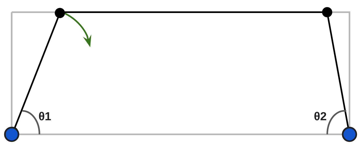
The setup shows 3 rigid links (with fixed lengths) constrained by 4 joints. The blue joints are fixed in place and only allow rotation, while the black joints can move and also allow rotation. Initially θ1 < θ2, and the top link is perfectly horizontal.

As θ1 decreases (due to the leftmost link rotating clockwise), it is clear that θ2 will increase, but I would like to get the specific value of θ2 as a function of θ1. Is there a name for this kind of problem? What would be the best software tool to simulate this?
$\endgroup$
2
  • $\begingroup$ No, I'm trying to approximate an Ackermann steering geometry, and this is technically the left half of the configuration. The idea is that a motor will rotate the rightmost fixed joint, increasing theta2 and therefore decreasing theta1. My problem is slightly more specific but this general problem should give me enough information to work out my issue. $\endgroup$
    – r0gi
    Commented Oct 4, 2021 at 22:38
  • $\begingroup$ Simple? No. I remember spending most of machine design on these stupid linkages. As I recall, matrices are used in the solutions. $\endgroup$
    – Tiger Guy
    Commented Oct 5, 2021 at 3:32

3 Answers 3

3
$\begingroup$

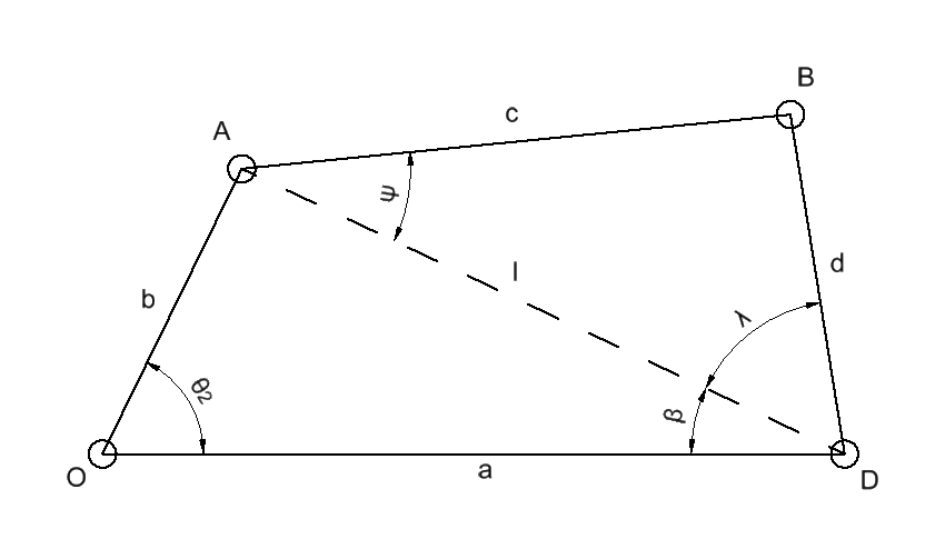
Since considering four-bar linkages is a useful tool in my research field, I happen to know of a paper that precisely solves what you want to do. George H. Martin published in 1958 in the journal Machine Design the paper "Four-Bar Linkages", the following equations are taken from that paper:

When you consider a four-bar linkage as shown below, then you know the angle $\theta _2$ and you want to know the angle that is the sum of $\beta$ and $\lambda$. Four-Bar Linkage Considering the triangle OAD, we can write $$ \beta = \sin^{-1} \left( \frac{b}{l} \sin \theta_2 \right).$$ So that is already the first half. For the triangle ABD, we can write $$ \psi = \cos^{-1} \left( \frac{c^2+l^2-d^2}{2cl} \right).$$ Using $\psi$, we can write $\lambda$ as $$ \lambda = \sin^{-1} \left( \frac{c}{d} \sin \psi \right).$$

With these, you should be able to work out a single equation for your problem.

$\endgroup$
1
$\begingroup$

I found a related question that is effectively asking the same question. This is typically known as a four bar linkage (I only drew three in my diagram since the 4th bar is static). As far as I can see, you can derive a trigonometric relationship between the angles, but it isn't exactly simple.

$\endgroup$
2
  • $\begingroup$ you did draw four, not three ... The blue joints are fixed in place $\endgroup$
    – jsotola
    Commented Oct 4, 2021 at 23:59
  • $\begingroup$ I should have been more specific, I meant that I only drew three solid 'beams' in black, with the fourth shaded gray. There are of course four joints in the diagram. $\endgroup$
    – r0gi
    Commented Oct 5, 2021 at 3:07
0
$\begingroup$

Any parametric cad software can create a sketch and then measure the angle as driven. See

  • onshape (browser based no need to install anything)
  • SOLIDWORKS
  • Siemens NX
  • CATIAetc

Also you can look at geogebra-geometry which is something that combines 2d algebra and geometry.

$\endgroup$
1
  • 1
    $\begingroup$ Add the free, multi-platform program SolveSpace for a great four-bar testing software. $\endgroup$
    – fred_dot_u
    Commented Oct 5, 2021 at 14:35

Your Answer

By clicking “Post Your Answer”, you agree to our terms of service and acknowledge you have read our privacy policy.

Not the answer you're looking for? Browse other questions tagged or ask your own question.