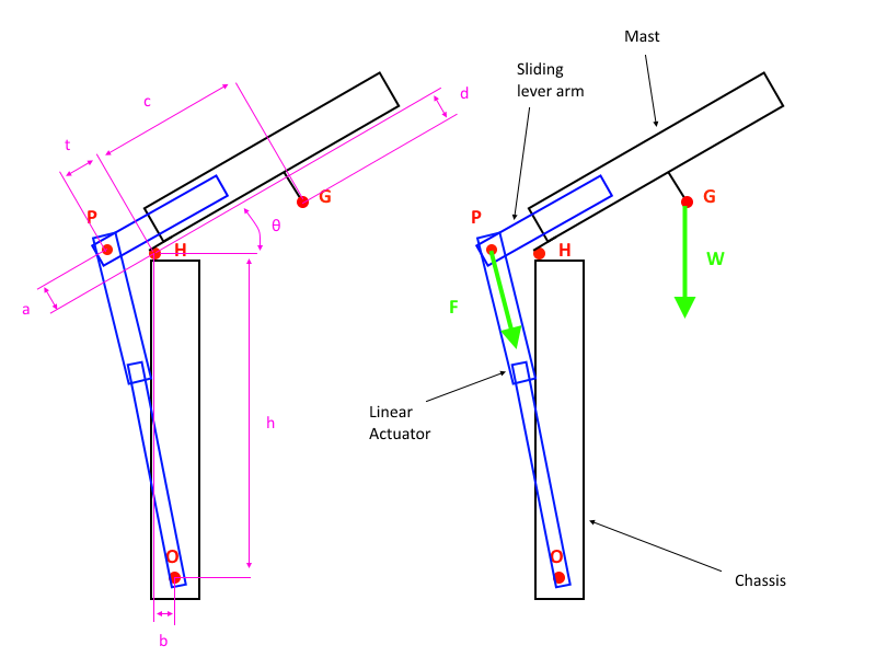
I'm designing a compact mechanism for the deployment of a mast. The idea is that the linear actuator for the deployment is on the other side of the pivot, and a slider increases the lever arm to enable the actuator to deploy the mast.
I ran through the maths (shown in details below), and wrote the code for the simulation. I want to know how the actuator force and the lever length relate, and how the force varies with the angle.

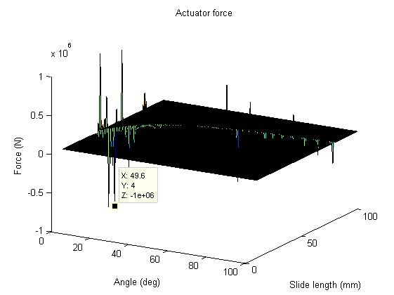
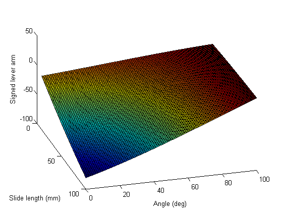
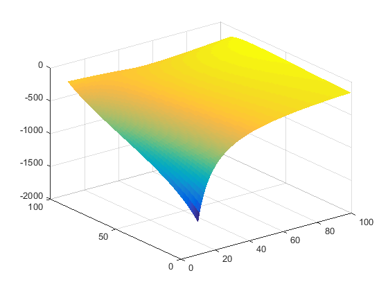
However, when I run the code I get huge spikes in the force (see below, I capped the force to 10^6 to better see the pattern), but for example I don't see why the mechanism would jam between 40 and 80°. For some reason the cross product of HP with OP (what I call the signed lever arm of F) goes through zero but I see no reason why it would given the current dimensions and angle range set. How can I fix it?
Original:
With the force capped at 200N:

And the denominator of F:
Annex
Code:
close all
clear all

%See diagram for description of variables, units are metres
a = (2+10)*10^-3;
b = a;
c = 165*10^-3;
d = 70*10^-3;
h = 180*10^-3;

m = 8; %Mass of the mast in kg
g = 9.81; %Acceleration of gravity in m/s²

%Range of the input variables
thetaMin = 0*pi/180;
thetaMax = 100*pi/180;
tMin = 10*10^-3;
tMax = 100*10^-3;

%Vectors
theta = thetaMin:(thetaMax-thetaMin)/100:thetaMax;
t = tMin:(tMax-tMin)/100:tMax;

%Solve for F
F = zeros(length(t), length(theta)); %Actuator force
L = F; %Length of linear actuator
denominator = F; %Denominator of F, or "signed lever arm"
for i = 1:length(t)
    for j = 1:length(theta)
        M = [cos(theta(j)) sin(theta(j)) 0;
             -sin(theta(j)) cos(theta(j)) 0;
             0 0 1];

        HP = M*[-t(i);
                a;
                0];

       OP = [-b;
              h;
              0]+HP;

       L(j,i) = norm(OP);

        HG = M*[c;
                -d;
                0];

        W = [0;
             -m*g;
             0];

        weightMoment = HG(1)*W(2)-HG(2)*W(1); %cross(HG,W)
        forceLever = 1/norm(OP)*(HP(1)*OP(2)-HP(2)*OP(1)); %1/norm(OP)*cross(HP,OP)

        denominator(j,i) = forceLever;

        F(j,i) = -weightMoment/forceLever;
    end
end

%Plot results
[T,THETA] = meshgrid(t,theta);

figure(1)
surface(T*1000,THETA*180/pi,F)
ylabel('Angle (deg)')
xlabel('Slide length (mm)')
zlabel('Force (N)')
title('Actuator force')

figure(2)
surface(T*1000,THETA*180/pi,L*1000)
ylabel('Angle (deg)')
xlabel('Slide length (mm)')
zlabel('Actuator length (mm)')

figure(3)
surface(T*1000,THETA*180/pi,denominator*1000)
ylabel('Angle (deg)')
xlabel('Slide length (mm)')
zlabel('Signed lever arm')
Maths: solve $$\vec{moment}(H)=\vec{HP}\times \vec{F}+\vec{HG} \times \vec {W}=\vec{0}$$ With $$\vec{F}=\frac{\vec{OP}}{OP}F$$ $$\vec{HP}= \left[ {\begin{array}{cc} cos(\theta) & sin(\theta) \\ -sin(\theta) & cos(\theta) \end{array} } \right] \left( {\begin{array}{cc} -t \\ a \end{array} } \right) $$ $$\vec{HG}= \left[ {\begin{array}{cc} cos(\theta) & sin(\theta) \\ -sin(\theta) & cos(\theta) \end{array} } \right] \left( {\begin{array}{cc} c \\ -d \end{array} } \right) $$ $$\vec{OP}=\vec{OH}+\vec{HP}$$ $$\vec{W}=\left( {\begin{array}{cc} 0 \\ -mg \end{array} } \right)$$ $$\vec{OH}=\left( {\begin{array}{cc} -b \\ h \end{array} } \right)$$


