0
$\begingroup$

The calculations for a design I am doing are making me go round in circles. I have simulated the design but I cannot seem to resolve this mathematically and it is really bugging me!

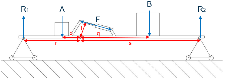
Below is an image of the design - two levers with different moments connected to each other by a hinge at their ends. Each lever's pivots can slide from left to right. The system equilibrium is maintained by an actuator between the two levers exerting a static force. This force is what I am trying to calculate.

I believe I need to work out the moment on each lever (easy enough) and resolve for a torque around the hinge point where the two levers are connected. From here I can calculate the force on the actuator using a free body diagram. Calculating the moment around the hinge point however is proving tricky as it is not as simple as just adding the two moments together (so my simulations tell me).

Note. Currently I am only interested in the static force to keep system in equilibrium.

I would appreciate the help.

Cheers
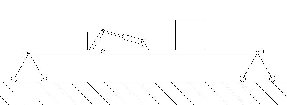
enter image description here

$\endgroup$
4
  • $\begingroup$ Tell us about your simulations? What did the simulation show? Does it make sense intuitively? $\endgroup$ Commented Sep 10, 2019 at 10:35
  • $\begingroup$ The reason you can't solve the problem is because your structure isn't stable. Even if the actuator has a fixed length, the two parts can still pivot around the ends. You have designed a 4-bar linkage. $\endgroup$
    – alephzero
    Commented Sep 10, 2019 at 11:16
  • 1
    $\begingroup$ I've assumed one of the two roller supports is fixed, but otherwise this seems OK to me? It would certainly be a four bar linkage if the LH and RH beams were not joined at the hinge underneath the (gas?) strut, but looks stable to me in its current incarnation. If you were to remove the strut entirely, it would just sag down at that hinge, requiring an upward reaction force to become horizontal again. Adding the strut doesn't change this - it just provides lift by trying to open up the hinge again, and effectively 'pushing' off the supports to create that lift - if you get what I mean... $\endgroup$ Commented Sep 10, 2019 at 11:42
  • $\begingroup$ Ah, sorry, I didn't zoom in on the drawing so I didn't see they were pinned under the strut. $\endgroup$
    – alephzero
    Commented Sep 10, 2019 at 12:48

2 Answers 2

1
$\begingroup$

I take the liberty of borrowing to the very nice diagram Jonathan has drawn to save time, please let me know if you are not OK with this Jonathan and I delete it. thank you.

diagram of the beam.

He has made a couple of small errors which we are going to fix.

We are going to Ignore the hinge and the jack and handle the beam as a straight beam with a length $l = r+s.$

  • Taking moments about $ R_1$ gives $ R_2= \frac{A(r-p)+B(r+q)}{r+s}$

  • Taking moments about $R_2$ gives $R_1= \frac{B(s-q)+A(s+p)}{r+s}$

Now we get the free body diagram of R1 to the hinge, including the force F acting at arm t of the jack.

$$ \Sigma M=0, \ t*F+ A*p-R_1*r=0 \\ tF= R_1*r-A*p \\ F= \frac{R_1*r-A*p}{t}$$

As a double check we could draw the right hand FBD. They should be the same. I leave calculating the shear at the hinge to you.

$\endgroup$
1
  • $\begingroup$ Oops! 🤦‍♂️ That'll teach me to proofread... (maybe)? $\endgroup$ Commented Sep 15, 2019 at 22:28
1
$\begingroup$

With no dimensions at all, things get real messy, real fast here - putting some numbers in should make things a whole lot cleaner. I'm in a rush and haven't proofread. That said, here goes:

Moments diagram labelled

Step 1 - find the reaction forces

  • Taking moments about $R_1$ gives $R_2=\frac{A(r-p)+B(r+q)}{r+s}$
  • Taking moments about $R_2$ gives $R_1=\frac{B(s-q)+A(s+p)}{r+s}$

Step 2 - take moments about the hinge

  • Looking left: $rR_1=pA+tF$ therefore $F=\frac{r\frac{B(s-q)+A(s+p)}{r+s}-pA}{t}$
  • Looking right: $sR_2=qB+tF$ therefore $F=\frac{s\frac{A(r-p)+B(r+q)}{r+s}-qB}{t}$

If you put in values there, how does it compare to your simulation?

EDIT: Fixed mathematical errors after @Kamran pointed them out!!

$\endgroup$
1
  • $\begingroup$ Thanks for the answers guys. What I failed to see was that both masses have an effect on both moments - I was treating them individually. I will do the calcs and compare and get back to you. $\endgroup$
    – WestyTea
    Commented Sep 15, 2019 at 13:39

Your Answer

By clicking “Post Your Answer”, you agree to our terms of service and acknowledge you have read our privacy policy.

Not the answer you're looking for? Browse other questions tagged or ask your own question.