13
$\begingroup$

I am making a device for measurements. I would like to measure the distance within accuracy of 1 mm. Range could be 2 cm to 15 cm . I looked at Proximity Sensors but the readings displayed by these sensors are not steady.

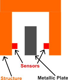
I wish to measure the thickness of the plate (carbon steel). The two sensors will be mounted on a structure. The sensors will give me the distance of the surface from the sensor. Then I will calculate the thickness of the plate.

What are possible types of low cost sensors I can use?

Sensor Arrangement

$\endgroup$
5
  • 1
    $\begingroup$ Hi JustCurious, welcome to engineering.SE. This is an interesting question, but it would be helpful to have more information. What are you measuring the distance between. Interferometric sensors, for instance, will give you significantly higher accuracy than 1 mm, but only work with certain surfaces. Your best bet for low cost is probably the type of proximity sensors used in the rear bumper of automobiles. $\endgroup$ Commented Apr 25, 2015 at 13:55
  • 1
    $\begingroup$ JustCurious, you still haven't really provided enough information to get a great answer. In particular, you may want to describe the goal, not the step. For instance, are you building a mobile robot, a 3D printer, or measuring tool? Are contact sensors allowed. Why are you trying to measure to 1mm accuracy over a range of 2cm to 15cm? $\endgroup$
    – regdoug
    Commented Apr 25, 2015 at 17:36
  • 2
    $\begingroup$ @regdoug Why does it matter if the sensor is on a robot or a 3D printer? It sounds like you have some answer in mind. Why don't you just post an answer with some pros and cons of the couple of different methods? This will make the answer valuable for others who aren't working on this exact project. $\endgroup$
    – hazzey
    Commented Apr 25, 2015 at 18:50
  • 1
    $\begingroup$ I don't really have an answer in mind, but the main reason that I said that is that a robot might have to deal with more complicated motion and objects than if say the sensor was only needed to zero a tool such as a 3D printer or cutter. I also get the sense that JustCurious doesn't have a solid list of performance requirements for this sensor, so detailing the application might let an answerer get a better sense of what might be required. $\endgroup$
    – regdoug
    Commented Apr 26, 2015 at 3:34
  • $\begingroup$ @JustCurious, you stated the sensor signal you tried were not steady. Why was this the case? Was the distance changing? Did you have look on a histogram of the signal, what was the S/N-ratio or the rel.standard-deviation? $\endgroup$
    – rul30
    Commented May 2, 2015 at 9:34

6 Answers 6

7
$\begingroup$

Answering the question:

What are possible types of low cost sensors I can use?

There are several types of sensors that can provide millimeter level accuracy. "Low cost" is a very relative term, so you'll need to do some shopping around based on your specific budget.

Optical sensors-

Included here are those of the type you listed, though it's a very cheap sensor meant more to provide a "yeah something is in front of me, about yay-far-away". There are also laser sensor systems which can provide millimeter level accuracy.

Ultrasonic Sensors-

Most ultrasonic sensors have relatively low accuracy; in the 25.4mm range. But some higher end sensors have sub-millimeter accuracy. Some are stand alone units with high accuracy.

Eddy current sensors-

These measure induced eddy currents and provide incredible accuracy.

Mechanical measurement-

It may be implied by your diagram, but it's not specified. Calipers are an obvious choice for measuring thickness. For a semi-automated approach you can also use linear displacement sensors.

$\endgroup$
5
$\begingroup$

Was looking for other distance solutions, and came across this question.

A sensor that I've found works well is the Sharp GP2Y0E02B (digital version) (newer version is the GP2Y0E03). Configuring it as an I2C sensor, using an Arduino, I've been able to get sub-millimeter resolution (0.156 mm - Range is ~630 mm, with 12 bit resolution).

Almost didn't believe it when I read the spec, so I put the sensor on a Bridgeport with a test target, and used this as 'ground truth'. Out to 50 mm on a simple test, the error was less than 0.2 mm; out at 100 mm, I got about a 0.4 mm error.

$\endgroup$
11
  • $\begingroup$ Hey, based on this comment I've purchased the GP2Y0E03 (I need ~mm accuracy) -- how have you configured yours over I2C? I'm not getting too much wiser from the poorly translated Japanese datasheet. Could you elaborate your readout method / code? $\endgroup$
    – John
    Commented Feb 8, 2021 at 0:22
  • $\begingroup$ For the code: forum.arduino.cc/index.php?topic=417651.0 ; for setting the fuse (to change the address, if necessary: github.com/martinpalsson/GP2Y0E02B_E-Fuse_Burner). To set the fuse is a bit tricky, I used an alligator clip with one side covered in tape, so you could touch the addressing pin. $\endgroup$
    – asylumax
    Commented Feb 9, 2021 at 2:31
  • $\begingroup$ Hey, thanks for the quick response! I've got two remaining questions: (1) In that code distance is also declared as an int, and printed in the serial monitor as a cm -- so how do you get mm accuracy? Or did you declare it as a float? (2) Changing the i2c address is necessary I assume if you want to run multiple of these units at the same time? $\endgroup$
    – John
    Commented Feb 10, 2021 at 12:50
  • $\begingroup$ Yep, distance as a float works. And yes, you can either change the i2c address, or use one of those i2c splitters so you don't have to change the address (typically, they are used for sensors which can't be changed). $\endgroup$
    – asylumax
    Commented Feb 11, 2021 at 2:53
  • $\begingroup$ Hey I'm trying it out now, but aren't you still 'moving' in increments of 0.25 cm // 2.5mm? distance[cm]=(byteHigh*16+byteLow)/16*0.25; with byteHigh between 0-255, byteLow 0-15, and everything *.25 if you set it to 64cm range (1/2^2). What I end up with is a summed value between 0-255, multiplied by 0.25; so 0cm-63.75cm.. Am I overlooking something here? $\endgroup$
    – John
    Commented Feb 11, 2021 at 11:39
2
$\begingroup$

Various solutions are possible depending on your exact requirements.

Contacting system

This is probably the most obvious system, consisting of 1 or 2 lever arms which are deflected by the plate. By measuring the deflection the size could be determined. The main drawback of this is that it is a contacting system which may be a problem depending on your setup.

Video system

Another alternative which would be simple to implement is a video system. Mount a camera above your sample and image the plate as it passes through. By either calibrating the camera before hand or mounting a line scale beneath the plate the size can be determined. Resolution will depend on resolution of the camera and scale, although I think 1 mm shouldn't be hard to achieve. This is probably what I would do if you didn't want a contact system.

Laser rangefinder

These may be possible depending on what you consider low cost. Most systems are based on time of flight, which limits the resolution to ~1 mm. Additionally most cheap systems I have seen have a minimum range of at least 5 cm, which may be too large for you.

Interferometer

Also may be possible. However, simple fringe counting methods have difficulties when measuring steps, so will probably not be suitable for measuring a plate (unless its infinite). Frequency scanning methods are possible, but probably don't fall under low cost, measurement speed may also be an issue depending on sample length and throughput required.
$\endgroup$
1
$\begingroup$

You haven't stated whether you want to get sensor readings into a computer or not. Also, it's not clear how frequent you need to do this task, and how much setup time is allowed per measurement.

If you want to do some Quality inspection (of whether the metallic plate is within tolerance bounds), you might want to consider simple or advanced image processing. for simple image processing, take a picture from front view and measure the distance between one end of the metal plate to the other end, or put a measurement paper behind the metal plate and take or observe the picture for measurement. If you have a human operator, this would probably be a simple way, just the accuracy requirement might be missed, depending on the setup of course.

Proximity sensors and other types of sensors might be effected by the movement of the metal plate, are you sure that it is not moving?

If you are sure about the alignment quality (that two surfaces are parallel), then you could push the plate to one side and use a regular micrometer or other measurement device.

$\endgroup$
0
$\begingroup$

The [MaxBotix HRLV MaxSonar-EZ][1] line (I'm looking at EZ4) claims to have a very steady analog output with 1mm accuracy, and has some supporting test documentation for their claims. About $40/sensor. I'd like the I2C version in order to eliminate analog weirdnesses in the circuitry as a factor, but so far the I2C ones only go to 1CM accuracy.

$\endgroup$
0
$\begingroup$

The RFD77402 (Qwiic) uses an infrared VCSEL (Vertical Cavity Surface Emitting Laser) module to measure the amount of time it takes to bounce off a target. This allows low-cost millimeter readings up to two meters.

SparkFun offers a breakout board for like 15 USD. The sparkfun board is not available as of 2022 (or earlier)

$\endgroup$
1
  • $\begingroup$ The SparkFun board is no longer available... $\endgroup$
    – MikeB
    Commented Aug 31, 2022 at 10:24

Your Answer

By clicking “Post Your Answer”, you agree to our terms of service and acknowledge you have read our privacy policy.

Not the answer you're looking for? Browse other questions tagged or ask your own question.