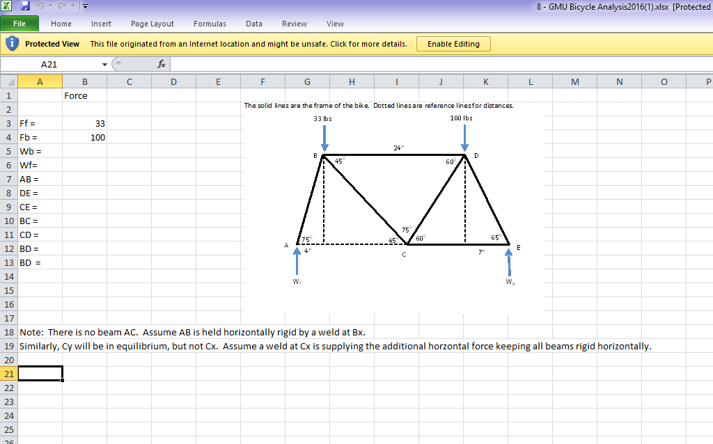
The problem is best understood with the text at top - that this is a frame for a bicycle, not a structure. Statics is not the correct method for approaching bicycle frames for a variety of reasons, but problem makers need to keep it interesting. Because it is a frame, none of the joints are truly pinned, which is why the welds are introduced. At a minimum, arm AB is welded in place on the frame to minimize the front wheel from pulling away from the front, or too close to the pedals. With this information, the problem could be approached several ways, from simple to insane, depending on your desired level of realism, and profit margins from building this bicycle:
- Add a single moment $B_z$ onto B. Summing moments about B should show how much arm AB is bending while the bike is moving. To reduce the problem to a truss problem, we will make the assumption that only member AB experiences bending. The bending is simple (see below). This isn't a good model for a variety of reasons, but it solves the problem on paper.
- As described in the paper add a reaction $B_x$ and $C_x$, which makes no intuitive sense. However, this is actually equivalent to answer 1 - which is why this type of problem is used frequently at end-of-term, it begins developing the concepts of strengths of materials. This method allows the use of statics techniques to solve it, but won't require a full strengths analysis. Summing forces in x directions will show $B_x$ = $-C_x$, and that the couple formed by these two reactions will have a moment equal to $B_z$.
- Realizing that the frame is still going to bend anyways (you already added a moment onto one member), turn this into a strengths problem, with all welds forming reactionary moments ($M = k*\theta$, k to be determined based upon weld length and material). An FEA would expedite the process. Note that deflection of A and E in y should be 0, as both tires should rest parallel to the ground.
- Realizing that the loading of a human onto the bicycle frame is probably more complex and distributed then the point loads shown (and more than likely has dynamic road loads, climbing loads, accelerations within and without of the plane, impact loadings, and that human pedal pushing will almost always necessitate the need for loading on node C.), build a bicycle, cover it with strain gauges, and measure performance with real humans to ensure all assumptions are accurate.
All of this goes back to the first method as a bare bones basis though. To begin, split $W_f$ into two components - one parallel to the member, and one perpendicular. Acting in the truss equations, the parallel reaction will carry through to the rest of the equations, while the perpendicular component is the bending force that will act to bend AB. Moment $B_z$ will need to exactly cancel this moment to ensure that only AB is experiencing bending, and the remaining members will undergo static deformations only. This will ensure that the weld load will make AB act in pure bending alone, otherwise all of the equations would need to be solved as bending equations, not as truss equations (method 3 above). Therefore:
$$B_z = W_f*\cos(75)*\frac{4in}{\cos(75)} = 4" * W_f$$
Then, summing moments about B:
$$B_z - 4in * W_f - 24in * 100 +31in * W_b = 0 \to W_b = \frac{100lb*24in}{31in} = 77.42lb$$
And summing forces in Y:
$$W_f+W_b-100lb-33lb = 0 \to W_f = \frac{133lb*31in - 100lb*24in}{31in} = 55.58lb$$
Which means $B_z = 55.58lb*4in = 222.32in*lb$, and the parallel portion of AB is simply $W_f*\sin(75) = 53.69lb$, which can then be put onto Node B, tilted at a 75 degree angle. The rest of the equations follow simple statics.
