0
$\begingroup$

I'm building a lumber rack similar to this, but in my case, the vertical supports (2x4s) will not lie against a wall. They will, however, be fixed at the top and bottom. I'm wondering roughly what the forces will be that will try to "bow" the vertical post since it won't have the support of a wall. My gut says the force will be different depending on how far below the pipe it is. Thus, I need an equation with a "y variable".

To keep things simple, you can assume all the weight on the pipe is at the end. Feel free to make any other simplifications (please state them). (I think this is a cantilevered beam problem, but when I searched, all I can find is how much the beam/pipe will deflect).

Here's a fixed example to help make things clear: if the vertical support is 48 inches tall and the pipe is 12 inches long with 10 pounds on it, how much weight/force will be applied against the vertical post 24 inches down (in the middle)?
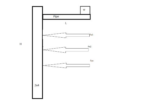
enter image description here

$\endgroup$

1 Answer 1

0
$\begingroup$

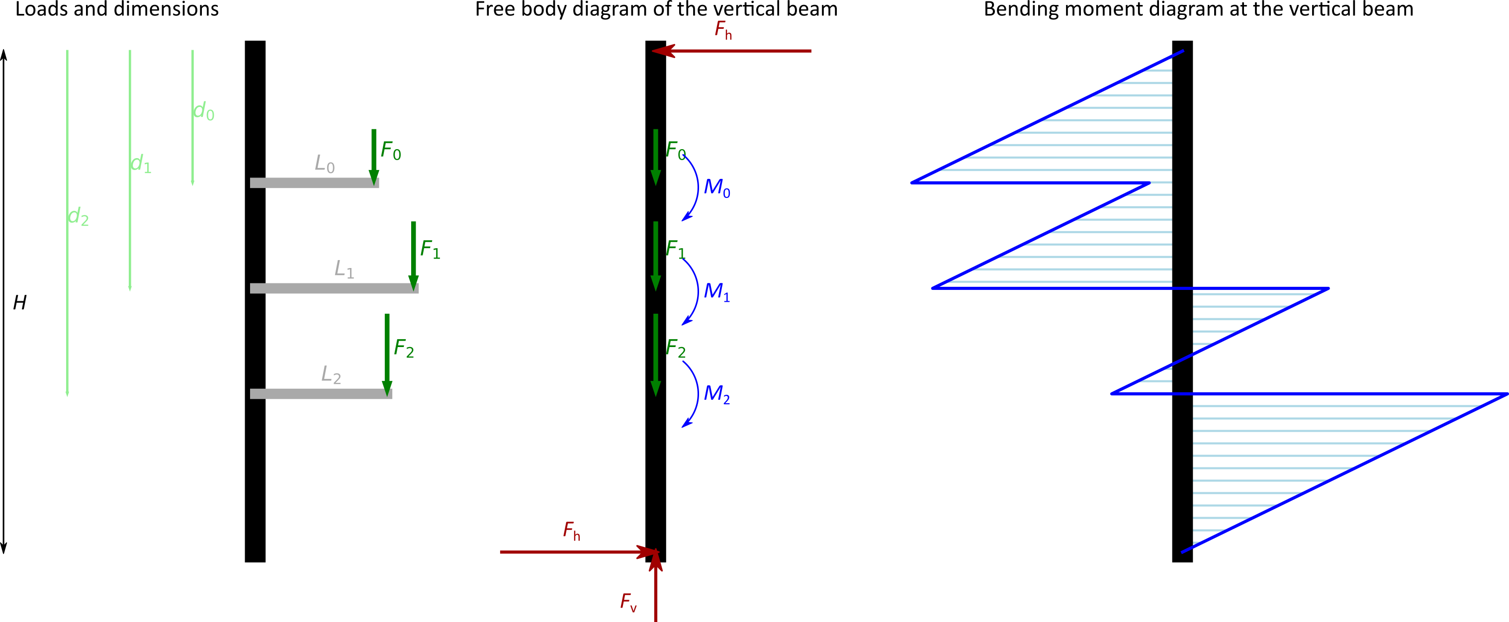
If top and bottom ends are pinned, the analysis is simple, as there will be only horizontal and vertical forces at these points. I will focus only one the horizontal ones, because you can treat the vertical forces separately and it is pretty straight-forward.

Each tube with its loading will transfer a vertical force and a bending moment to the vertical beam. Here, the force is $F_i$ and the moment $M_i$ is $F_i\cdot L_i$, but you could also consider for example self weight of the tubes.

Top and bottom horizontal force should have the same magnitude and opposite direction, so I denoted them both as $F_h$. You can calculate magnitude of $F_h$ from the moment equilibrium (here to the bottom end point): $$F_h\cdot H = \sum_{i=0}^3 F_i\cdot L_i$$ From that: $$F_h = \frac{\sum_{i=0}^3 F_i\cdot L_i}{H}$$

Now you can make the bending moment diagram. Starting from top, the force $F_h$ at the top will cause moment $F_h\cdot d$ as you go to a distance $d$ from the top (constant slope) and the individual moments from the tubes will cause 'jumps' in the opposite direction. Extreme bending stress combined with axial stress from vertical forces can be used to check the design. As you can see, the extremes should be only at the connections of horizontal tubes

enter image description here

If one of the ends or both are fixed, the analysis would be more complicated and the bending moments would be lower. So even for such case, if moments from the above analysis are acceptable, they would be even more safe with fixed ends.

$\endgroup$
5
  • $\begingroup$ Thanks for letting me know it's a complicated thing--I suspected that after I failed to find anything. I know what you mean by pinned and that your "approximation" of my "system" will result in higher values. This is OK because I'm just doing a sanity check. $\endgroup$ Commented Nov 27, 2022 at 18:25
  • $\begingroup$ What a pain--I tried to put a CR in it and comment got submitted. Then because of formatting attempts, it took longer than 5 minutes to do the edit. Here's the rest: I have some questions on your answer. In the equations, is "F" my "W"? And is F_hd the green "F"s in your diagram (vertical forces)? $\endgroup$ Commented Nov 27, 2022 at 18:33
  • $\begingroup$ $F$ is vertical force from self weight, so it could be $w$ if it is a force. Fh in the figure is $F_h$ in the equations (I did some last minute mspaint editing :)). It should also be on the bottom end with reversed direction. This force "couple" acts against moments from weights. $\endgroup$ Commented Nov 28, 2022 at 16:55
  • $\begingroup$ Thanks. My attempt at math formatting failed. I'll try again using just text. Is the product ("F sub h") * d the green Fs you have in the diagram? I think these are moment forces (I'm beyond my physics knowledge) and I believe they relate to the horizontal force(s) I'm interested in. If so, how do I go from these vertical downward forces to the horizontal ones? $\endgroup$ Commented Nov 30, 2022 at 21:27
  • $\begingroup$ Not really. When you go from top to bottom and you are at a distance $d$, it will make a bending moment $F_h\cdot d$ in the vertical support. The forces $F$ from the horizontal pipes will transfer certain bending moment $F\cdot L$ (and vertical force $F$) at the connection, which acts in the opposite way to the moment from $F_h$, so this causes a "jump" in the bending moment diagram. $\endgroup$ Commented Dec 1, 2022 at 15:49

Your Answer

By clicking “Post Your Answer”, you agree to our terms of service and acknowledge you have read our privacy policy.

Not the answer you're looking for? Browse other questions tagged or ask your own question.